Aprilaire 1710A, 1750A, and 1770A Dehumidifier Troubleshooting Manual
Comprehensive troubleshooting guide for Aprilaire 1710A, 1750A, and 1770A dehumidifiers, covering fault codes, capacity verification, water leak resolution, and electrical diagnostics.
Table of contents
Troubleshooting Fault Codes
The Aprilaire 1710A, 1750A, and 1770A dehumidifiers use a red Fault LED on the control board to indicate issues. The number of blinks corresponds to specific faults:
- 1 blink: Thermistor signal issue. Inspect sensor arm pins and control board socket.
- 2 blinks: RH sensor signal issue. Inspect sensor arm pins and control board socket.
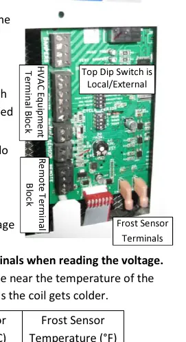
- 3 blinks: Communication loss with Model 70 or 76 control. Verify wiring and terminal tightness.
- 4 blinks: Frost sensor indicates suction line temperature has not dropped sufficiently. Check compressor operation and refrigeration system.
- 5 blinks: Incoming air temperature is outside the 50°F–100°F range.
- 6 blinks: Frost sensor signal out of range. Check connections and sensor integrity.
- 7 blinks: Float switch input is open. Check for water in the drain pan or faulty switch.
Verifying Capacity
If the unit is running but not removing sufficient moisture, verify performance by measuring inlet and outlet air temperature and relative humidity. Use the provided performance graphs to calculate moisture removal. Ensure the unit is in local mode and the control knob is set to the highest setting (7) for testing. Note that the compressor will not engage if the dew point is below 40°F.
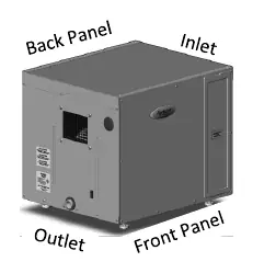
Water Leaks
Water leaks are often caused by improper drainage. Ensure the unit is level side-to-side and has a slight slope toward the drain. Use only the provided custom running trap to prevent air-locks in the negative pressure cabinet. Regularly clean the drain trap and tubing, ensuring a continuous downward slope.
Electrical Troubleshooting
If the blower or compressor fails to function, verify the power supply (120 VAC). Inspect the power board for scorched or cracked components, specifically the varistor. Use a digital multi-meter to check the run capacitor (55 µF for 1710A/1750A, 60 µF for 1770A) and verify continuity of the high temperature switch. Warning: Do not measure resistance or continuity of the high temperature switch while it is connected to the power board, as this may cause damage.
Circuit Breaker Trips
Ensure the dehumidifier is on a dedicated circuit appropriate for its load (15A for 1710A/1750A, 20A for 1770A). If the breaker trips, inspect electrical connections at the power board, contactor, and run capacitor for loose wires or shorts.

Manual page author
Michael Turner
Technical manual editor
Reviews PDF manuals for structure, safety notes, and practical product details so readers can find the right information quickly.