1097A Filter Description and Use
Comprehensive guide for the 1097A narrowband filter, detailing its operation with the 147C amplifier for precise tone identification and noise filtering in telecommunications testing.
Table of contents
Manual images
Jump to the sectionProduct Overview
The 1097A filter is a specialized narrowband filter designed specifically for use with the 147C amplifier. Its primary function is to facilitate accurate toning and pair identification in environments where electrical noise or power line interference is present. By filtering out unwanted electrical noise, the device ensures that the test tone remains clear and audible.
Technical Requirements
The 1097A filter is precisely tuned to a frequency of 577.5 Hz. For optimal performance, it must be used in conjunction with a precision tone source, such as the KS-14103 L6 breakdown test set or the 138A test set. Using an ordinary tone source will result in unsatisfactory and intermittent operation. The filter is housed in a compact, molded plastic case and features a permanently attached cord and plug assembly.
Installation and Power
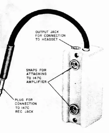
The 1097A filter does not contain its own batteries. Instead, it is powered directly by the 147C amplifier through the REC jack. To install, simply snap the filter onto the side of the 147C amplifier and insert the plug into the REC jack. Please note that the 1097A filter is only compatible with the 147C amplifier; it will not function with the 147B amplifier as it does not provide the necessary battery voltage. To conserve battery life, always unplug the filter from the amplifier when the equipment is not in use.
Operation and Adjustment
Proper adjustment of the amplifier-filter combination is essential for best performance. The recommended procedure involves adjusting the gain of the 147C amplifier while listening to the noise level before the filter is inserted. Once the gain is set, the 1097A filter is connected, and the tone source is adjusted to a usable level. In electrically noisy environments, the tone level should be set higher, while in quiet areas, a lower setting is sufficient. Once these adjustments are complete, the system is ready for fault location and pair identification operations.
Manufacturer information
AT&T
Practical help
Common problems
Ensure you are using a precision tone source like the 138A or KS-14103 L6 test set, not an ordinary tone source.
Verify that the filter is connected to a 147C amplifier. It is not compatible with the 147B amplifier.
Before use
- Ensure the 147C amplifier battery is charged.
- Verify the use of a precision tone source.
- Snap the filter onto the side of the 147C amplifier.
- Plug the filter cord into the REC jack of the amplifier.
- Adjust amplifier gain before inserting the filter.
- Connect the headset to the filter output jack.
Specs in practice
- Tuning Frequency
- 577.5 Hz, the specific frequency the filter is designed to isolate.
- Power Source
- Derived from the 147C amplifier via the REC jack connection.
Images and diagrams
- Fig 1 shows the physical layout of the 1097A filter, including the output jack for the headset and the plug for the amplifier.
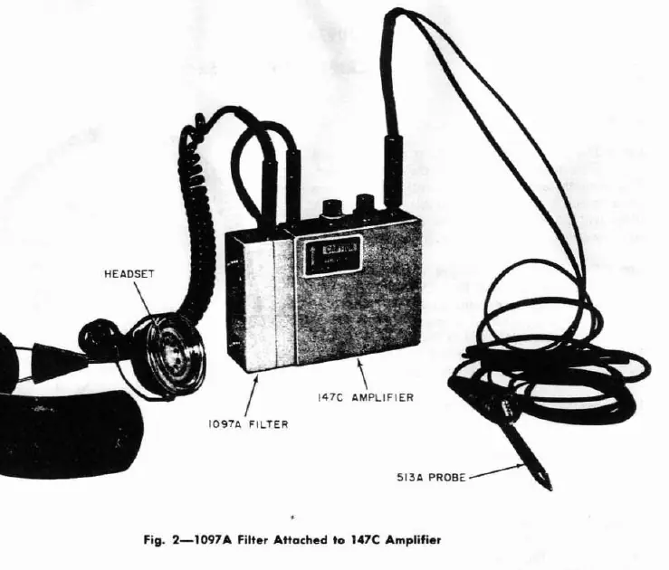
- Fig 2 illustrates the complete setup with the filter attached to the 147C amplifier and the probe connected for testing.
Model compatibility
- Compatible only with the 147C amplifier.
- Not compatible with the 147B amplifier due to voltage requirements.

Manual page author
David Miller
Documentation analyst
Organizes user manual content into clear summaries, with attention to model details, product context, and everyday usability.