User Manual for AV Access 8KEX100-KVM 8K KVM Extender
Quick guide for the AV Access 8KEX100-KVM 8K KVM Extender. Includes installation, panel descriptions, DIP switch settings, and technical specifications.
Table of contents
Manual images
Click an image to enlargeQuick Guide
The AV Access 8KEX100-KVM is an 8K transmitter and receiver kit designed to extend 8K video and USB 2.0 signals up to 328ft (100m) over a single Cat 6/6A/7 cable. It supports HDMI 2.1, HDCP 2.3, and HDR10.
Package Contents
- Extender Set (Transmitter and Receiver)
- Power Adapter (DC 12V 3A)
- USB 2.0 Type-A to Type-B Cable
- 3.5mm 3-pin Phoenix Male Connectors (x2)
- 3.5mm 5-pin Phoenix Male Connector
- Mounting Brackets with Screws
- User Manual
Device Overview
Transmitter Panel
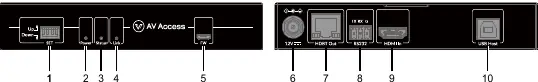
The transmitter features a 4-pin SET switch for configuration, Power/Status/Link LEDs, a Micro USB port for firmware updates, a 12V power input, HDBT Out, RS232 port, HDMI In, and a USB Host port.
Receiver Panel
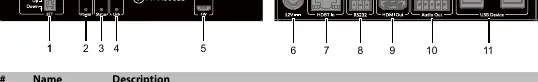
The receiver features a 2-pin SET switch, Power/Status/Link LEDs, a Micro USB port, 12V power input, HDBT In, RS232 port, HDMI Out, Audio Out, and 4 USB 2.0 Type-A ports for peripherals.
Installation and Application
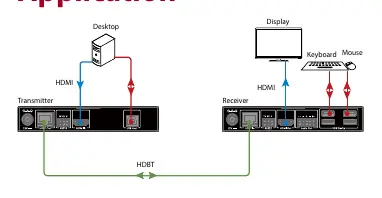
Connect your HDMI source to the Transmitter's HDMI In port and your USB host (e.g., PC) to the USB Host port. Connect the Transmitter to the Receiver using a Cat 6/6A/7 cable via the HDBT ports. Connect your display to the Receiver's HDMI Out port and USB peripherals to the USB Device ports. Power can be supplied to either unit using the included 12V adapter, as the system supports one-way PoC (Power over Cable).

RS-232 Operation
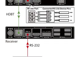
The RS-232 ports support bidirectional data passthrough. Before operation, ensure that pin 1 of the SET switches on both the transmitter and receiver is set to the "Up" position.
DIP Switch Configurations
Transmitter
The 4-pin SET switch configures RS-232 mode, input HDCP, and input EDID. By default, all pins are set to "Up".
- RS-232: Up for passthrough (default), Down for firmware updates.
- HDCP: Up for On (default), Down for Off.
- EDID: Various settings available for Copy EDID (default), 4K@60, 4K@30, and 1080P@60.
Receiver
The 2-pin SET switch configures RS-232 mode. Pin 1 Up is default (passthrough), Down is for firmware updates. Pin 2 is reserved.
Specifications
- Resolution: Up to 8K@60Hz 4:2:0, 8K@30Hz 4:4:4, and 4K@120Hz.
- Transmission Distance: Up to 328ft (100m) via Cat 6/6A/7; 295ft (90m) via Cat 5e.
- Power: DC 12V 3A, supports PoC.
- Audio: Supports multichannel audio up to PCM 7.1, Dolby Atmos, DTS:X, etc.
Support
For technical support or general enquiries, contact AV Access via email at [email protected] or [email protected].
Practical help
Common problems
Check the HDBT cable connection between the transmitter and receiver. Ensure the cable is Cat 6/6A/7 and within the 100m range.
Ensure the power adapter is properly connected and the device is powered on. Verify the power source.
Ensure pin 1 of the SET switch on both the transmitter and receiver is set to the 'Up' position.
Before use
- Verify all package contents are present.
- Ensure you have a high-quality Cat 6/6A/7 cable for the HDBT connection.
- Check that your HDMI source and display support the desired resolution.
- Confirm the power adapter is connected to either the transmitter or receiver (PoC will power the other unit).
- Set DIP switches according to your specific setup requirements (e.g., EDID, HDCP).
Specs in practice
- PoC (Power over Cable)
- Allows a single power adapter connected to either the transmitter or receiver to power both units.
- RS-232 Passthrough
- Allows serial data communication between the transmitter and receiver for control systems.
Images and diagrams
- Transmitter Panel: Identifies ports for 12V power, HDBT Out, RS232, HDMI In, and USB Host.
- Receiver Panel: Identifies ports for 12V power, HDBT In, RS232, HDMI Out, Audio Out, and USB Device.
- Application Diagram: Illustrates the connection flow from PC to Transmitter, via HDBT cable to Receiver, and out to Display/Peripherals.
Model compatibility
- Supports Cat 6/6A/7 cables up to 100m.
- Supports Cat 5e cables up to 90m.
- HDMI 2.1 compliant.
- USB 2.0 extension supported.

Manual page author
David Miller
Documentation analyst
Organizes user manual content into clear summaries, with attention to model details, product context, and everyday usability.