BEA 900 MHz Wireless Transmitters and Receivers
Comprehensive installation and programming guide for the BEA 900 MHz wireless transmitter and receiver family, including standard, industrial, and retrofit models.
Table of contents
Product Overview
The BEA 900 MHz wireless family consists of various transmitters and receivers designed for door activation. The system includes standard, industrial (NEMA 4), and universal series, as well as specialized retrofit transmitters for touchless applications. The receiver features a tri-color LED for signal strength indication, learn buttons for programming, and a delay potentiometer.
Safety and Installation
Important: This wireless receiver is not intended for direct connection to Maglocks or Electric Strikes due to potential damage from inductive load kickback. Always use a Logic Module (e.g., Br3) or an Isolation Relay. Ensure all power is disconnected before wiring. Circuit boards are sensitive to electrostatic discharge (ESD); handle with care. Compliance with local safety standards like ANSI A156.10/19 is required upon completion.
Wiring and Configuration
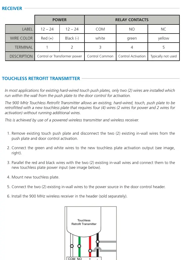
The receiver operates on 12-24 VAC/VDC. Wiring terminals include power (1, 2), common (3), normally open (4), and normally closed (5). The 900 MHz Touchless Retrofit Transmitter allows upgrading existing hard-wired push plates to touchless operation without running new wires by utilizing the existing two-wire path for power and activation.
Programming
Programming is performed using the learn buttons on the receiver. DIP switches on the receiver allow for configuring relay behavior: pulse vs. toggle mode, hold times (0.5s or 10s), and standard vs. extended hold. For hand-held transmitters, press the learn button on the receiver and then press the transmitter button twice. Vestibule configurations allow specific transmitters to trigger specific receivers with or without delay.
Maintenance and Troubleshooting
Low battery is indicated by three transmitter LED blinks after pressing the button. Replace batteries according to the specific model (CR2032 for hand-held, AAA for push plates). If experiencing weak signals, ensure the receiver antenna is positioned outside the door header. For constant activation issues, check for obstructions near touchless sensors or verify that the system is not set to Toggle Mode.
Contact
For technical support, contact BEA, Inc. at 1-800-523-2462 or email [email protected]. Additional documentation is available at www.BEAsensors.com.
Official resources from the manual
Manufacturer information
BEA Sensors
Practical help
Common problems
Ensure the receiver antenna wire is positioned outside of the door header.
Check for a stuck push plate or a faulty transmitter by disconnecting them one by one.
Clear the area in front of the sensor, ensure it is not connected to NC, and verify it is set to Pulse Mode.
Verify power and activation wiring connections at the transmitter, plate, and door control.
Before use
- Remove the plastic pull-tab from the transmitter to enable battery connection.
- Ensure the receiver is not connected directly to Maglocks or Electric Strikes.
- Dissipate body ESD charge before handling circuit boards.
- Verify that all wiring is disconnected from power before starting installation.
- Check that moving door parts will not catch any wires.
Specs in practice
- Input Voltage
- 12 – 24 VAC / VDC.
- Contact Rating
- Maximum load capacity: 1.0 A @ 30 VDC, 0.3 A @ 60 VDC, or 0.5 A @ 125 VAC.
- Operating Temperature
- Functional range from 14 to 131 °F (-10 to 55 °C).
Images and diagrams
- Receiver interface: Includes antenna, activation/learn LEDs, signal strength indicator, DIP switches, and delay settings.
- Touchless Retrofit wiring: Shows how to connect the transmitter to the touchless plate and existing in-wall wires.
- Vestibule configuration: Illustrates how to assign specific transmitters to inner and outer receivers for proper door sequencing.
Model compatibility
- Industrial transmitters are IP65/NEMA 4 rated.
- Standard transmitters require 10TD900PB for push plate applications.
- All devices comply with FCC and IC regulations.

Manual page author
Michael Turner
Technical manual editor
Reviews PDF manuals for structure, safety notes, and practical product details so readers can find the right information quickly.