User Manual for Bogen NEAR Signature S4T/S5T Speakers
Quick guide for Bogen NEAR Signature S4T and S5T speakers. Includes instructions for power tap selection, 70V and low-impedance wiring, wall-mounting procedures, safety cable attachment, and maintenance.
Table of contents
Manual images
Click an image to enlargeQuick guide from the manual
This document provides installation and configuration instructions for the Bogen NEAR Signature S4T and S5T speakers. Key tasks include selecting the correct power tap, wiring for 70V or low-impedance systems, and secure wall mounting.
Power Tap Selection
The speakers feature a tap selector to adjust power settings. Ensure the selector is set correctly based on your system requirements.
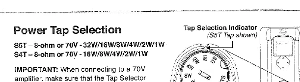
- S5T: 8-ohm or 70V (32W/16W/8W/4W/2W/1W)
- S4T: 8-ohm or 70V (16W/8W/4W/2W/1W)
- Important: When connecting to a 70V amplifier, ensure the Tap Selector is not in the 8-ohm position.
Speaker Connections and Polarity
To connect the speakers:
- Strip approximately 1/2 inch of insulation from the wires.
- Push down on the spring clamps and insert the wire into the hole, then release the clamp.
- Maintain proper polarity by connecting black terminals to black and red terminals to red on the same speaker run.
System Configurations
70V System
When designing a 70V system, the total of all power tap settings of all connected speakers cannot exceed the output power of the 70V amplifier. The amplifier power can exceed the sum of the speaker loads.
Low-Impedance System
When wiring multiple speakers set to 8 ohms, calculate the total load using Ohm's Law. The total load impedance of the interconnected speakers cannot be lower than the minimum load impedance rating of the amplifier. Ensure the amplifier cannot overdrive the speaker's maximum power rating.
Wall-Mounting Instructions
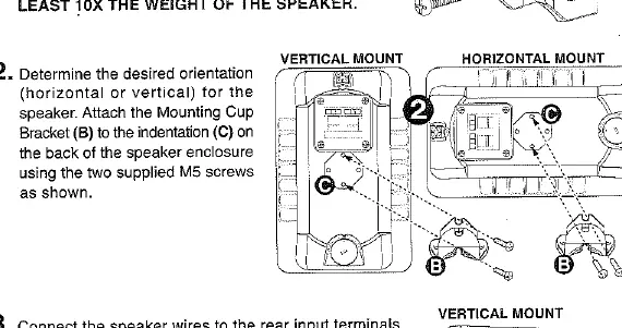
- Secure Mounting Base: Attach the Mounting Base (A) to the wall. The wall material and user-supplied hardware must be able to resist a pull-out force of at least 10 times the weight of the speaker.
- Attach Bracket: Determine the desired orientation (horizontal or vertical). Attach the Mounting Cup Bracket (B) to the indentation (C) on the back of the speaker using the two supplied M5 screws.
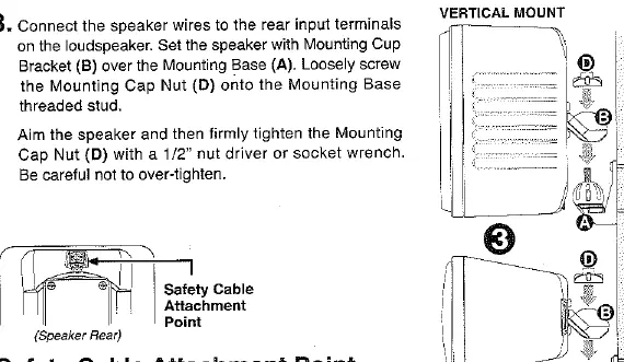
- Mount Speaker: Connect the speaker wires to the rear input terminals. Set the speaker with the Mounting Cup Bracket (B) over the Mounting Base (A). Loosely screw the Mounting Cap Nut (D) onto the Mounting Base threaded stud. Aim the speaker and firmly tighten the Mounting Cap Nut (D) with a 1/2 inch nut driver or socket wrench. Do not over-tighten.
Safety and Maintenance
Safety Cable: The speakers provide an attachment point for a user-supplied safety cable. This cable must be attached to an anchor independent of the speaker mounting hardware and rated to withstand a force 10 times greater than the weight of the speaker.
Care: Clean the speaker cabinet using only soap and water with a soft cloth.
Manufacturer information
Bogen Communications
Practical help
Common problems
Ensure the sum of all speaker tap settings does not exceed the amplifier's rated output power.
Calculate total load using Ohm's Law; ensure total impedance is not lower than the amplifier's minimum rating.
Verify the Tap Selector is not set to 8-ohm when using a 70V amplifier.
Before use
- Strip 1/2 inch of insulation from wires.
- Verify amplifier type (70V vs Low-Impedance).
- Set the Tap Selector to the appropriate wattage or 8-ohm setting.
- Ensure wall mounting surface can support 10x the speaker weight.
- Prepare a safety cable for independent attachment.
Specs in practice
- 8-ohm (Low-Impedance)
- Standard speaker connection; requires careful impedance calculation when connecting multiple units.
- Tap Settings
- Adjustable power levels (1W to 32W) for 70V operation to balance volume across speakers.
Images and diagrams
- Wiring diagrams show how to connect speakers in parallel for both 70V and low-impedance configurations.
- Mounting diagrams illustrate the assembly of the Mounting Cup Bracket and the use of the Mounting Cap Nut for both vertical and horizontal orientations.
Model compatibility
- Compatible with 70V amplifiers (ensure total load < amplifier power).
- Compatible with low-impedance amplifiers (ensure total load > amplifier minimum impedance rating).

Manual page author
Michael Turner
Technical manual editor
Reviews PDF manuals for structure, safety notes, and practical product details so readers can find the right information quickly.