General / Service Manuals
Bosch GSR 12V-30 Drill/Driver Exploded View and Parts Guide
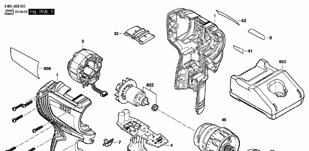
Detailed exploded view diagram and technical specifications for the Bosch GSR 12V-30 drill/driver, including torque settings and component identification for maintenance and repair.
Table of contents
Quick guide from the manual
This document provides an exploded view diagram of the Bosch GSR 12V-30 drill/driver. It is intended for service personnel and users performing maintenance or repairs. The diagram identifies individual components and specifies critical torque settings required for reassembly.
Exploded view and components
The diagram illustrates the internal structure of the tool, including the motor, gearbox, electronic control unit, and housing components. Each part is numbered for identification. Key components shown include the drill chuck, motor assembly, electronic module, and housing shells.
Torque specifications
Proper torque is essential for the safe and functional assembly of the tool. Refer to the following specifications when tightening fasteners:
- Pos. 25 (Chuck): Greater than 15 Nm
- Pos. 101 (Housing screws): 0.9 - 1.1 Nm (requires T10 bit)
- Pos. 107 (Chuck screw): 5.0 - 8.0 Nm (requires T25 bit)
Maintenance and repair
When disassembling the tool, ensure all internal wiring is routed correctly to avoid pinching or damage during reassembly. Use only original Bosch replacement parts to maintain the tool's performance and safety standards. Always remove the battery pack before performing any maintenance or disassembly.
Manufacturer information
Bosch
Practical help
Common problems
Loose drill chuck
Check the chuck screw (Pos. 107) and tighten to 5.0 - 8.0 Nm using a T25 bit.
Housing not closing properly
Ensure all internal components (motor, electronics, gearbox) are seated correctly in the housing shells before tightening the 8 housing screws (Pos. 101).
Before use
- Ensure the battery is removed before starting any disassembly.
- Verify you have the correct Torx bits (T10 and T25) for the specified torque requirements.
- Organize all small parts (screws, springs) to prevent loss during the repair process.
Specs in practice
- Pos. 101 Torque
- 0.9 - 1.1 Nm is the required torque for the housing screws using a T10 bit.
- Pos. 107 Torque
- 5.0 - 8.0 Nm is the required torque for the chuck screw using a T25 bit.
- Pos. 25 Torque
- The drill chuck must be tightened to at least 15 Nm.
Images and diagrams
- The diagram shows the tool split into its primary housing halves.
- The motor and gearbox assembly are shown as central components.
- The electronic module is positioned between the motor and the battery interface.
Model compatibility
- This diagram is specific to the Bosch GSR 12V-30 model (3 601 JG9 000).

Manual page author
David Miller
Documentation analyst
Organizes user manual content into clear summaries, with attention to model details, product context, and everyday usability.