Bosch GSR 18V-150 C Parts Diagram and Torque Specifications
Access the official exploded view diagram and torque specifications for the Bosch GSR 18V-150 C cordless drill. This guide helps identify components and provides critical torque settings for proper assembly and maintenance.
Table of contents
Exploded View and Parts Identification
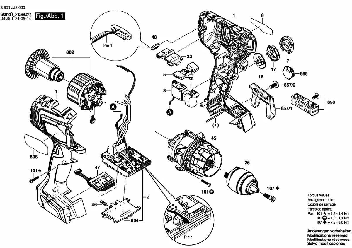
This document provides a detailed exploded view diagram of the Bosch GSR 18V-150 C cordless drill. It is intended for service technicians and users performing maintenance or repairs. The diagram illustrates the internal and external components, including the motor, chuck, electronic control module, and housing assembly.
Torque Specifications
Proper torque is critical during reassembly to ensure the structural integrity and safety of the tool. Use a calibrated torque wrench to tighten the specified screws to the following values:
- Pos 101: 1.2 - 1.4 Nm
- Pos 107: 7.5 - 9.0 Nm
Component Overview
The diagram identifies key assemblies, including the motor (802), the chuck (25), the electronic control module (4), and the housing components (808). Ensure all parts are correctly aligned and that electrical connectors (marked as Pin 1) are properly seated before securing the housing screws.
Manufacturer information
Bosch
Practical help
Common problems
Use a torque wrench to ensure screws (Pos 101 and 107) are tightened to the specified Nm range to prevent housing damage or loose components.
Ensure all internal components, particularly the electronic module (4) and motor (802), are fully seated in their respective housing slots before closing the casing.
Before use
- Verify all components are present before starting assembly.
- Use a calibrated torque wrench for all specified screws.
- Ensure the electronic module (4) is correctly seated.
- Check that the motor (802) is properly aligned with the housing.
- Verify electrical connections (Pin 1) are secure.

Manual page author
Michael Turner
Technical manual editor
Reviews PDF manuals for structure, safety notes, and practical product details so readers can find the right information quickly.