Parts Diagram for Bosch GST 12V-70 Jigsaw
View the official exploded parts diagram for the Bosch GST 12V-70 jigsaw. Identify components, assembly structure, and reference numbers for maintenance and repair.
Table of contents
Quick guide from the manual
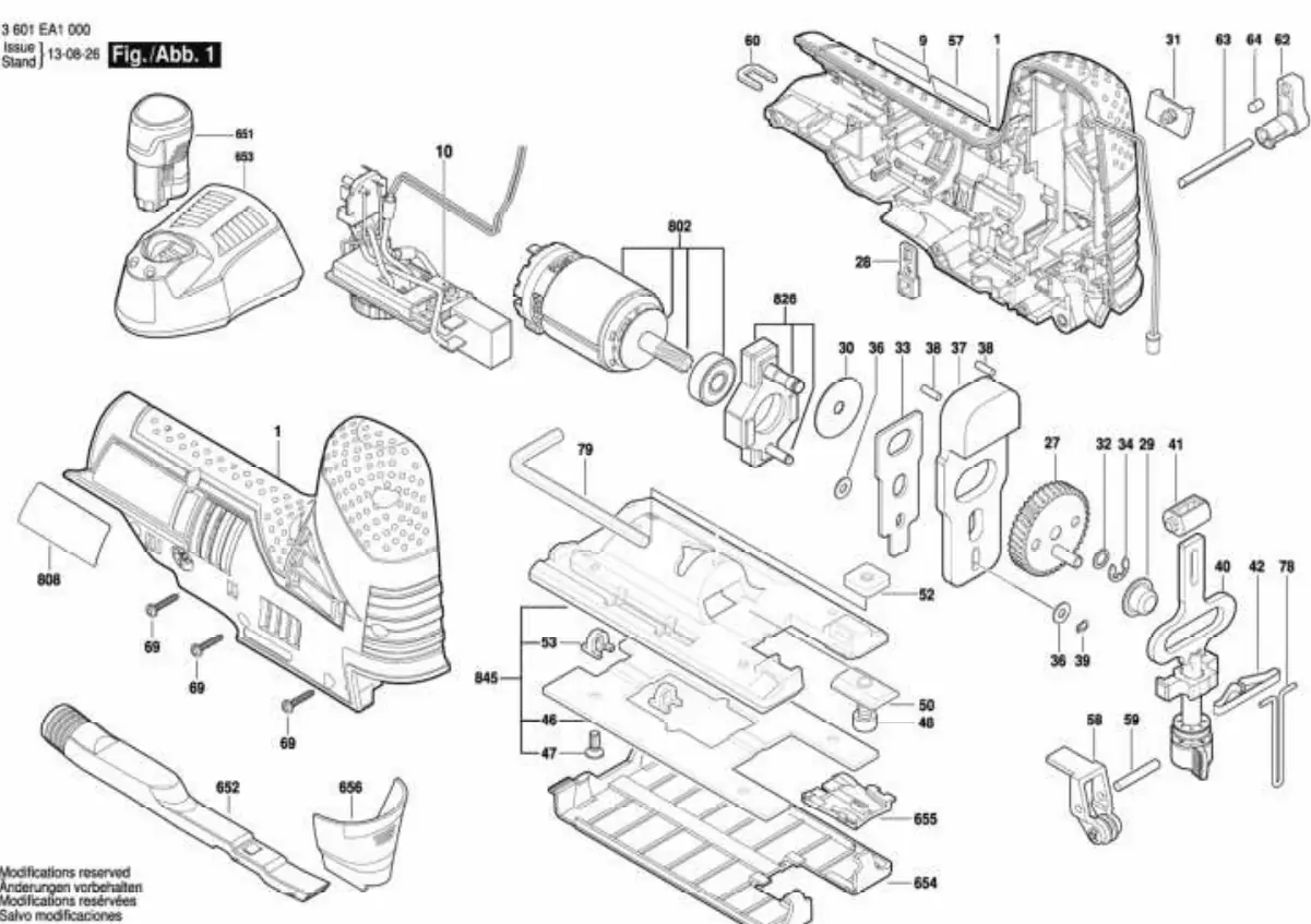
This document provides an official exploded view diagram for the Bosch GST 12V-70 jigsaw. It is intended for service technicians and users performing maintenance or repairs. The diagram illustrates the assembly of the tool, allowing for the identification of individual components and their relative positions.
Exploded View Diagram
The diagram (Fig. 1) displays the complete assembly of the Bosch GST 12V-70. Key components visible include the motor (802), the housing (1), the base plate assembly (845), and various internal gears and electrical components. Use this reference to locate specific parts when ordering replacements or reassembling the tool.
Maintenance and Repair
When using this diagram for repairs, ensure the battery is removed from the tool before disassembly. Keep all small parts organized during the process to prevent loss. If you are unsure about the assembly or disassembly of specific internal components, consult a professional service center.
Manufacturer information
Bosch
Practical help
Common problems
Use the reference numbers in the diagram to match parts with the official Bosch spare parts catalog.
Refer to the exploded view to ensure all gears, washers, and housing components are placed in the correct order.
Before use
- Disconnect the battery pack before performing any maintenance.
- Prepare a clean, well-lit workspace.
- Use appropriate tools for disassembly.
- Organize removed screws and small parts to avoid loss.

Manual page author
Michael Turner
Technical manual editor
Reviews PDF manuals for structure, safety notes, and practical product details so readers can find the right information quickly.