Parts Diagram for Bosch GSR 12V-30 Drill
Access the official exploded view diagram and parts list for the Bosch GSR 12V-30 drill. Includes torque specifications for assembly and component identification.
Table of contents
Quick Guide from the Manual
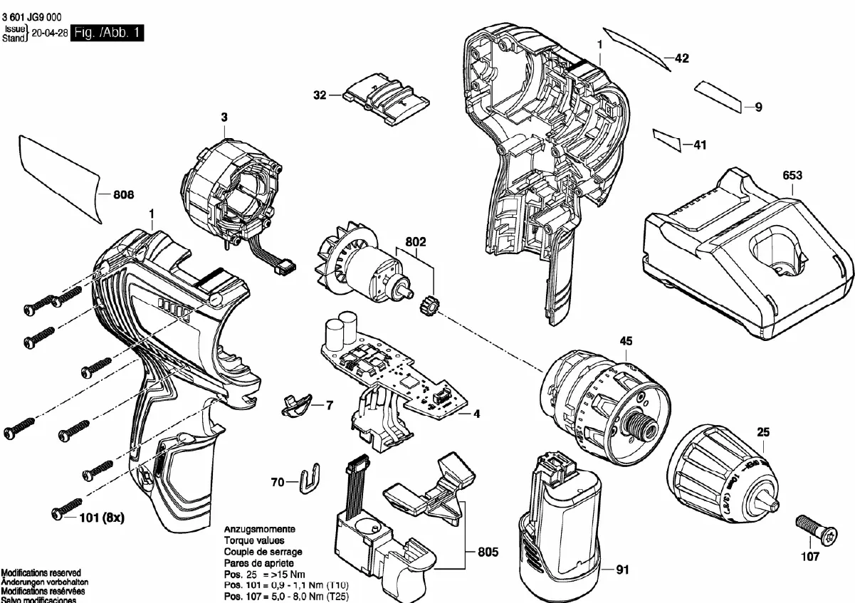
This document provides the official exploded view diagram for the Bosch GSR 12V-30 drill. It is intended for service, maintenance, and repair purposes. Use this diagram to identify individual components and ensure correct assembly using the specified torque values.
Exploded View and Component Identification
The diagram illustrates the drill disassembled into its primary components, including the motor, housing, chuck, and internal electronics. Each part is numbered to assist in identifying specific replacement components. Ensure you have the correct parts before beginning any disassembly or repair.
Torque Specifications
Proper torque is critical for the safe and functional reassembly of the drill. Refer to the following specifications provided in the diagram:
- Pos. 25 (Chuck Assembly): Greater than 15 Nm.
- Pos. 101 (Housing Screws): 0.9 - 1.1 Nm (requires T10 driver).
- Pos. 107 (Chuck Screw): 5.0 - 8.0 Nm (requires T25 driver).
Manufacturer information
Bosch
Practical help
Common problems
Tighten the screws (Pos. 101) to a torque of 0.9 - 1.1 Nm using a T10 driver.
Secure the chuck screw (Pos. 107) to 5.0 - 8.0 Nm using a T25 driver. The chuck assembly (Pos. 25) requires >15 Nm.
Before use
- Ensure the battery is removed from the tool before attempting any disassembly.
- Verify you have the correct Torx drivers (T10 and T25) for the specified screws.
- Organize all removed parts to prevent loss during the repair process.
- Check the diagram to ensure all components are accounted for before reassembly.

Manual page author
David Miller
Documentation analyst
Organizes user manual content into clear summaries, with attention to model details, product context, and everyday usability.