User Manual for BWI Eagle Air-Eagle XLT 441-12000-120VAC Transmitter
Comprehensive user guide for the BWI Eagle Air-Eagle XLT 441-12000-120VAC transmitter. Includes installation instructions, terminal wiring diagrams, frequency and repeater mode configuration, and technical specifications.
Table of contents
Manual images
Click an image to enlargeQuick Guide
The Air-Eagle XLT 441-12000-120VAC is a 900MHz dry contact input transmitter designed to send up to 20 independent commands to compatible receivers. Before installation, ensure power is disconnected. The unit is user-programmable for eight network frequencies and supports a repeater mode. Always verify wiring connections against the terminal strip labels before applying power.
Product Description
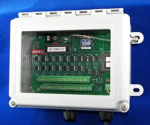
The Air-Eagle XLT is a spread-spectrum RF transmitter capable of operating in noisy RF environments. It features 20 dry contact inputs and a range of up to 2500 feet with the standard antenna. The unit is housed in a NEMA 4, 12, and 13 rated fiberglass enclosure.
Installation
- Mount the transmitter in a convenient, suitable location.
- Install wiring to the contact input terminal strip.
- Configure frequency and repeater mode settings (see Frequency & Repeater Setup).
- Install the antenna onto the connector located on the top of the enclosure.
- Connect the supplied power input cable to your external power source.
Wiring
The unit features two terminal blocks for inputs and one for AC power. Ensure all wiring is secure.
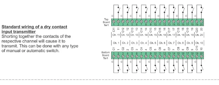
- Bottom Terminal Block: Inputs 1-10 (C and N/O for each).
- Top Terminal Block: Inputs 11-20 (C and N/O for each).
- AC Input Terminal Block: 120 VAC Neutral and 120 VAC Hot.
Standard wiring for dry contact inputs involves shorting the contacts of the respective channel. For common ground applications, inputs can be wired to share a common (C) terminal.
Frequency and Repeater Setup
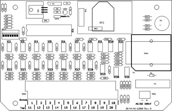
The unit is factory-shipped with SEL1 switches in the open position (Frequency #1, Repeater Mode OFF). To change settings:
- Remove power from the unit.
- Remove the top cover.
- Adjust SEL1 switches according to the table below.
- Reattach the cover and apply power.
Repeater Mode
- SW4 Open: Repeater Mode OFF (Default).
- SW4 Closed: Repeater Mode ON.
Frequency Selection (SW5-7)
- Frequency 1: All Open.
- Frequency 2: SW5 Closed, SW6/7 Open.
- Frequency 3: SW6 Closed, SW5/7 Open.
- Frequency 4: SW5/6 Closed, SW7 Open.
- Frequency 5: SW7 Closed, SW5/6 Open.
- Frequency 6: SW5/7 Closed, SW6 Open.
- Frequency 7: SW6/7 Closed, SW5 Open.
- Frequency 8: All Closed.
Note: Switches 1 through 3 are not used on this model and should remain OPEN.
Specifications
- AC Input: 120 VAC, 16 W, 50/60 Hz.
- RF Frequency: 900 MHz Spread Spectrum.
- Input Channels: 20 Dry Contact Inputs.
- RF Output Power: 250 mW.
- Transmitter Range: Up to 2500 feet (varies by terrain and interference).
- Operating Temperature: -40°F to +185°F.
- Enclosure: Fiberglass / NEMA 4, 12 + 13.
Accessories
The following accessories are available for the Air-Eagle XLT:
- Standard Antenna: 900MHz TNC “Rubber Duck” Antenna (49-1103).
- High Gain Antennas: Various Omni-Directional and Yagi antennas available for extended range.
- Coax Cables: High-quality cables available in various lengths.
- Bulkhead Extensions: For mounting the control unit inside another enclosure.
Warranty
BWI Eagle Inc. warrants the system to be free from defects in material and workmanship for 1 year after the date of purchase. This warranty covers repair or replacement but does not cover damage due to external causes, misuse, or improper installation. Contact BWI Eagle for a return material authorization.
Practical help
Common problems
Ensure power is connected, the antenna is properly installed, and the frequency settings match the receiver.
Range is an estimate based on free-air terrain. Obstructions like walls, metal objects, trees, and hills will reduce range. Ensure the antenna is mounted high and clear of obstructions.
Before use
- Disconnect power before installation.
- Mount the transmitter in a convenient location.
- Verify wiring to the terminal strip.
- Set frequency and repeater mode using SEL1 switches.
- Install the antenna on the top connector.
- Connect the power input cable.
Specs in practice
- RF Frequency
- 900 MHz Spread Spectrum technology for secure communication.
- Transmitter Range
- Up to 2500 feet in ideal conditions; actual range varies based on terrain and interference.
- Operating Temperature
- Suitable for environments between -40°F and +185°F.
Images and diagrams
- Terminal Strip Wiring: Shows the layout for connecting 20 dry contact inputs and AC power.
- Frequency & Repeater Setup: A table detailing the switch positions for 8 different network frequencies and repeater mode activation.
Model compatibility
- Compatible with Air-Eagle Receivers.
- Supports up to 20 independent commands.

Manual page author
Michael Turner
Technical manual editor
Reviews PDF manuals for structure, safety notes, and practical product details so readers can find the right information quickly.