Carrier 14SEERYAC-01SUP Single-Packaged Air Conditioner and Gas Furnace System Supplemental Instructions
Essential supplemental instructions for the Carrier 14SEERYAC-01SUP single-packaged air conditioner and gas furnace system, focusing on gas pressure testing, manifold pressure adjustment, and gas input calibration for natural gas units.
Table of contents
System Overview and Safety
This document provides supplemental instructions for the Carrier 14SEERYAC-01SUP single-packaged air conditioner and gas furnace system. These units are designed for natural gas operation. Important: This unit is not compatible with standard propane conversion kits; contact your distributor for a specific replacement gas valve if conversion is required. Failure to follow installation and adjustment procedures can result in fire hazards, property damage, or personal injury. Always ensure that all pressure tap set screws are tightened and pipe plugs are properly installed to prevent gas leaks.
Checking Inlet Gas Pressure
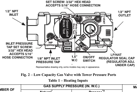
Inlet gas pressure must be verified while the furnace is operating in gas heat mode to ensure it remains within the range specified on the unit's rating plate. The process involves:
- Turning off the gas supply and electrical power to the unit.
- Loosening the inlet tower pressure tap set screw and connecting a manometer using a 5/16-inch hose.
- Restoring power and gas supply, then jumpering the R and W thermostat connections to initiate a call for heat.
- Verifying the pressure reading once the main burners ignite.
- Removing the manometer, disconnecting the hose, and securely tightening the set screw after testing.
Adjusting Gas Input
Gas input is calibrated by measuring gas flow at the meter or by adjusting the manifold pressure. For natural gas units, the manifold pressure must be maintained between 3.2 and 3.8 inches W.C.
Measuring and Adjusting Flow
- Ensure all other gas appliances connected to the same meter are turned off during measurement.
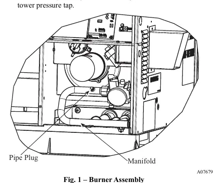
- Measure manifold pressure by removing the pipe plug on the manifold or using the tower pressure tap.
- Calculate gas flow by timing the gas meter test dial and using the heating value of the gas.
- Adjust the manifold pressure by removing the regulator cover screw and turning the plastic adjustment screw clockwise to increase input or counterclockwise to decrease it.
- After adjustments, replace the regulator cover, remove the manometer, and perform a final leak check on all connections.