Installation Guide for Central Heating Dual Clima HT Heat Pump
Quick installation guide for Central Heating Dual Clima HT heat pumps (12HT and 16HT models). Includes dimensions, clearance requirements, electrical connection specifications, and fitting kit assembly details.
Table of contents
Manual images
Click an image to enlargeQuick Guide
This document provides essential installation information for the Central Heating Dual Clima HT heat pump series. It covers physical dimensions, required clearances, condensate management, fitting kit assembly, and electrical supply requirements. Always refer to the full installation manual for comprehensive details.
Dimensions and Connections
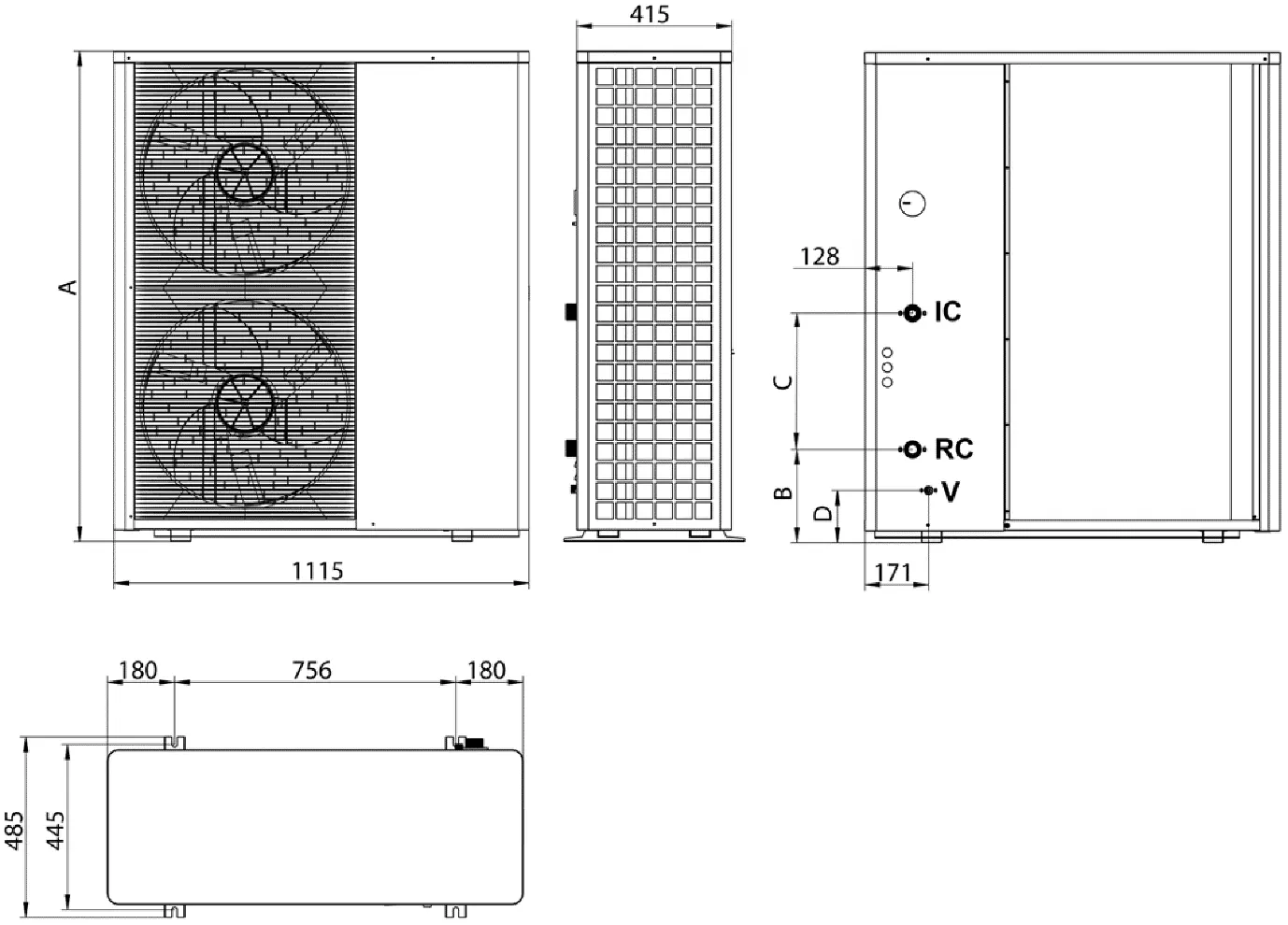
The heat pump dimensions vary by model. For the 12HT model, the height (A) is 898mm, B is 140mm, C is 476mm, and D is 62mm. For the 16HT model, the height (A) is 1320mm, B is 466mm, C is 150mm, and D is 140mm. Hydronic port sizes for the 12HT are 1" Male for Flow and Return, and 1/2" Male for Drain. For the 16HT, they are 1-1/4" Male for Flow and Return, and 1/2" Male for Drain.
Installation Clearances
To ensure proper operation and airflow, specific minimum clearances must be maintained around the unit:
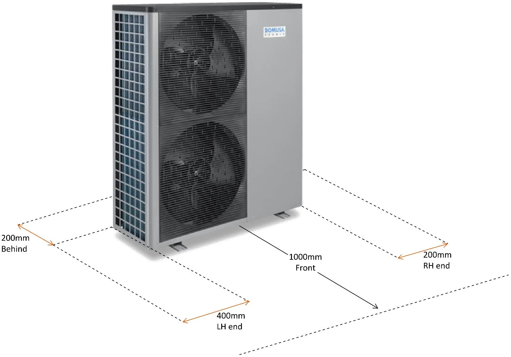

- Front: 1000mm
- Left Hand (LH) end: 400mm
- Right Hand (RH) end: 200mm
- Behind: 200mm
The unit must be mounted on anti-vibration feet at least 80mm off the ground to allow for airflow and prevent debris buildup.
Condensate Management
Condensate should be managed to prevent slip hazards, especially in winter when it may freeze. It can be piped to a soak pit or a free drain if a strip drain is used. Use the supplied drain pan fitting for connection.
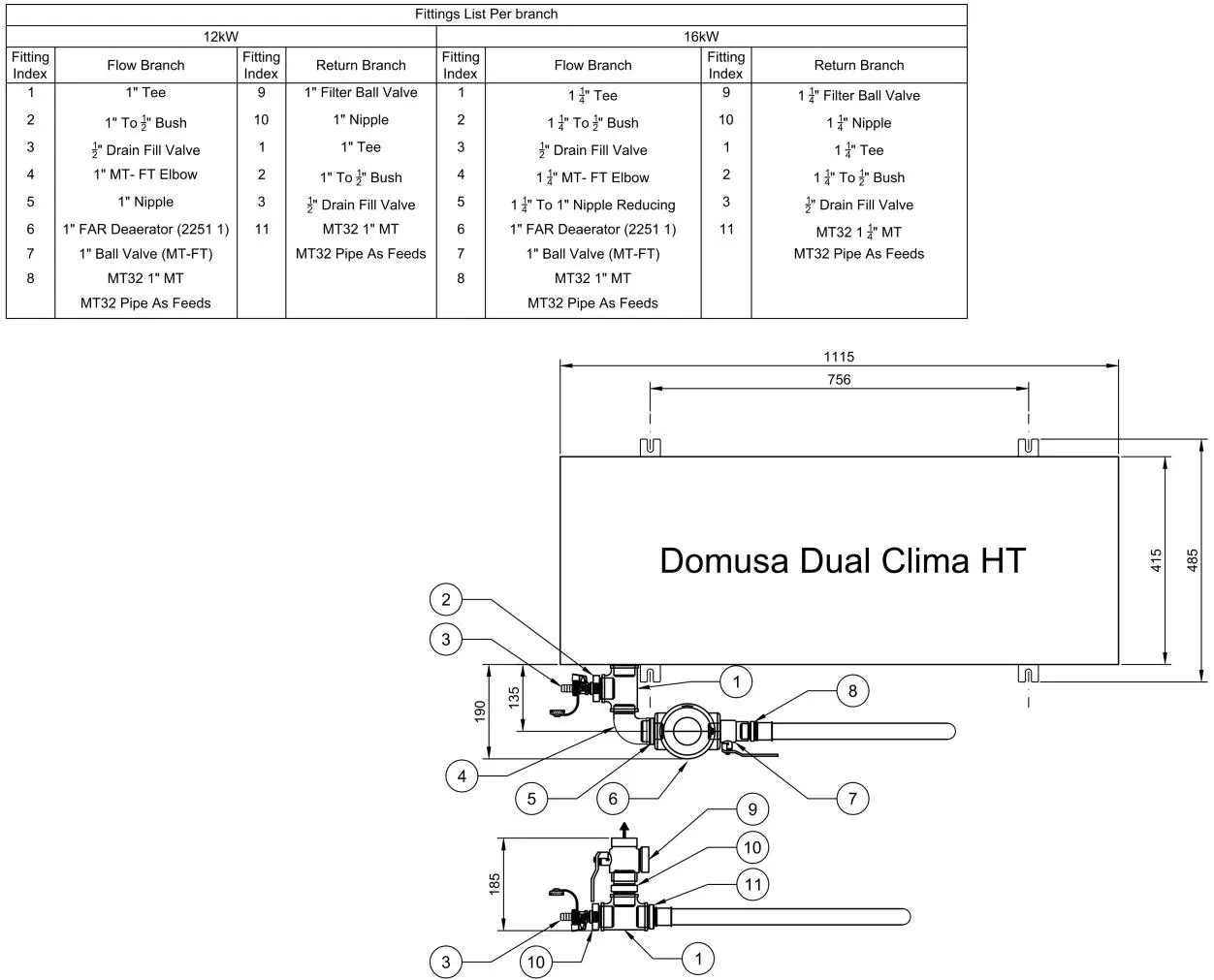
Fitting Kit Assembly
The installation requires the use of specific fitting kits (HPFIT16D or HPFIT12D). A mandatory deaerator (FARDEAR1) must be installed on the primary flow to mitigate the risk of refrigerant entering the system water in the event of a heat exchanger failure. All fittings should be threaded to the bottom threads where possible, using thread sealing products like Loctite 55 or Hemp and Hawk White. Insulation of the fitting kit is required.
Electrical Connections
Both models operate on a 230VAC 50Hz single-phase supply. The 12HT model requires a 4mm2 cable and a 25A fuse, with a maximum current draw of 17A. The 16HT model requires a 6mm2 cable and a 32A fuse, with a maximum current draw of 27A.
Safety and Warnings
For underfloor installations, ensure the flow temperature does not exceed 50°C to prevent damage to flooring materials. A warning sticker is provided to be placed on the controller bezel. Maintain safe distances from ignition sources (1.5m for generators and potential ignition sources, 0.5m for electrical isolator switches Before commissioning, scan the QR code provided in the manual or visit the Central Heating website to access the full Commissioning Guide. For further assistance, contact [email protected].Commissioning
Practical help
Common problems
Make provisions to manage condensate drainage to prevent slip hazards.
For underfloor heating, ensure flow temperature does not exceed 50°C. Apply the provided warning sticker to the controller.
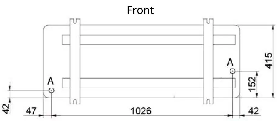
Use the HPKANTVIBR anti-vibration mounting feet to adjust each corner of the heat pump.
Before use
- Verify minimum clearances: 1000mm front, 400mm LH, 200mm RH/behind.
- Mount unit on anti-vibration feet at least 80mm off the ground.
- Install the mandatory deaerator on the primary flow.
- Ensure electrical supply matches model requirements (230VAC).
- Insulate the fitting kit components.
- Check that the deaerator bleed cap is left open.
Specs in practice
- 12HT Max Current
- 17A (requires 4mm2 cable and 25A fuse).
- 16HT Max Current
- 27A (requires 6mm2 cable and 32A fuse).
- 12HT Capacity
- 12kW.
- 16HT Capacity
- 16kW.
Images and diagrams
- Dimensions diagram: Shows port locations and physical measurements for 12HT and 16HT.
- Clearance diagram: Illustrates required spacing around the heat pump unit.
- Fitting kit diagram: Details the assembly sequence for flow and return branches.
Model compatibility
- Fitting kits HPFIT16D and HPFIT12D are model-specific.
- If no buffer tank is used, pipe length limits may be reduced.
- Radiator systems do not require the high flow temperature warning sticker.

Manual page author
Emily Carter
User documentation editor
Prepares concise manual descriptions and highlights the most useful setup, operation, and maintenance information for readers.