Installation Guide for Danfoss ECA 30/31 Frame Kit
Quick installation guide for the Danfoss ECA 30/31 Frame Kit (code 087H3236). Includes step-by-step mounting instructions, wall cutout dimensions, and assembly sequence.
Table of contents
Installation Guide for Danfoss ECA 30/31 Frame Kit
This document provides installation instructions for the Danfoss ECA 30/31 Frame Kit (code no. 087H3236). This kit is designed for mounting ECA 30 or ECA 31 controllers into a wall or panel.
Installation Steps
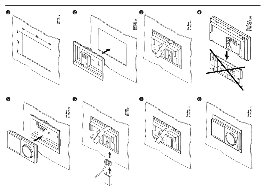
- Prepare the wall cutout with dimensions of 139 mm x 93 mm.
- Insert the frame into the prepared opening.
- Secure the frame in place.
- Ensure the controller unit is ready for connection.
- Align the controller with the frame.
- Connect the necessary cables to the controller.
- Snap the controller into the frame securely.
- Verify the final assembly is flush and stable.
Technical Specifications
The frame kit has the following external dimensions:
- Width: 144 mm
- Height: 96 mm
- Depth: 28 mm
Support
For further assistance, visit the official Danfoss website at www.heating.danfoss.com or check the installation videos on the Danfoss Heating YouTube channel.
Official resources from the manual
Manufacturer information
Danfoss A/S
Practical help
Before use
- Verify the wall cutout dimensions are exactly 139 mm x 93 mm.
- Ensure all necessary cabling is accessible at the installation site before mounting.
- Check that the controller unit is compatible with the ECA 30/31 frame.
Images and diagrams
- The installation diagram illustrates an 8-step process starting from the wall cutout preparation to the final snap-in assembly of the controller.

Manual page author
David Miller
Documentation analyst
Organizes user manual content into clear summaries, with attention to model details, product context, and everyday usability.