Danfoss EVRA Size 25 Inspection Kit Installation Guide
Quick guide for the Danfoss EVRA size 25 inspection kit (032F2326). Includes an exploded view diagram and a detailed list of included seals and gaskets for valve maintenance.
Table of contents
Quick guide from the manual
This document serves as a spare parts identification guide for the Danfoss EVRA size 25 inspection kit (Code number 032F2326). It provides an exploded view of the valve assembly and identifies the specific seals and gaskets included in the kit to assist with maintenance and repair procedures.
EVRA Size 25 Inspection Kit Components
The inspection kit contains the following components, which should be verified before beginning any maintenance work:
- Part 1: Ø14 mm, Aluminum (Total quantity: 1)
- Part 2: Ø27 mm, Aluminum (Total quantity: 1)
- Part 3: Ø10 mm, Aluminum (Total quantity: 1)
- Part 4: Ø6.07 mm, Rubber (Total quantity: 1)
- Part 5: Ø66 mm, Rubber (Total quantity: 1)
- Part 6: Ø39 mm, Fibre (Total quantity: 2)
- Part 7: Ø5.28 mm (Total quantity: 1)
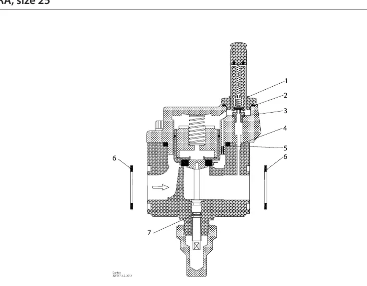
Assembly Diagram
The provided diagram illustrates the internal structure of the EVRA size 25 valve. The numbered parts in the diagram correspond to the components listed above. Ensure that the valve is fully depressurized and isolated from the system before attempting to disassemble the unit or replace any seals.
Manufacturer information
Danfoss A/S
Practical help
Common problems
Refer to the exploded diagram to ensure each seal (1-7) is placed in its correct corresponding position within the valve assembly.
Verify the contents of the kit against the list provided in the manual (e.g., ensure there are 2 pieces of the Ø39 mm Fibre seal).
Before use
- Confirm the valve model is EVRA size 25.
- Verify the kit code is 032F2326.
- Ensure the system is completely depressurized before starting maintenance.
- Clean the valve seating surfaces before installing new seals.
- Check that all required seals (1-7) are present.

Manual page author
Emily Carter
User documentation editor
Prepares concise manual descriptions and highlights the most useful setup, operation, and maintenance information for readers.