Installation Manual for Danfoss Icon Floor Sensor 088U1110
Quick installation guide for the Danfoss Icon Floor Sensor (088U1110). Learn about proper conduit mounting, bending radius requirements, and optimal placement between heating loops.
Table of contents
Important Installation Information
This document provides essential installation guidelines for the Danfoss Icon Floor Sensor (088U1110). Proper installation is critical for the functionality and future maintenance of the sensor.
Installation Requirements
To ensure the sensor can be replaced if necessary, follow these installation standards:
- Conduit System: Use conduit systems for electrical installations in accordance with EN/IEC 61386-23.
- Mounting: The floor sensor must be mounted in an insulating conduit.
- Sealing: The conduit must be sealed at the floor end to facilitate easy replacement of the sensor.
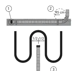
- Bending Radius: The minimum bending radius for the conduit is 5 cm.
Optimal Placement
For the most accurate temperature readings, the floor sensor should be positioned centered between two floor heating loops.
Electrical Safety
The floor sensor is a LIVE cable. Any extension made to the sensor wiring must be treated in the same way as normal mains voltage cabling.
Technical Specifications
- Type: NTC 47 kΩ / 25°C
- Cable Length: 3 m
Manufacturer information
Danfoss A/S
Practical help
Common problems
Ensure the sensor is installed in an insulating conduit sealed at the floor end to allow for easy removal.
Treat the sensor cable as a live cable; extensions must comply with mains voltage cabling standards.
Before use
- Verify conduit system complies with EN/IEC 61386-23.
- Ensure the conduit is sealed at the floor end.
- Check that the bending radius is at least 5 cm.

Manual page author
Emily Carter
User documentation editor
Prepares concise manual descriptions and highlights the most useful setup, operation, and maintenance information for readers.