Installation Guide for Danfoss Gas Sensor Strobe and Horn
Installation and configuration guide for the Danfoss Gas Sensor Strobe and Horn. Includes wiring diagrams for DC and AC power, tone selection table, and technical specifications.
Table of contents
Manual images
Jump to the sectionQuick Guide
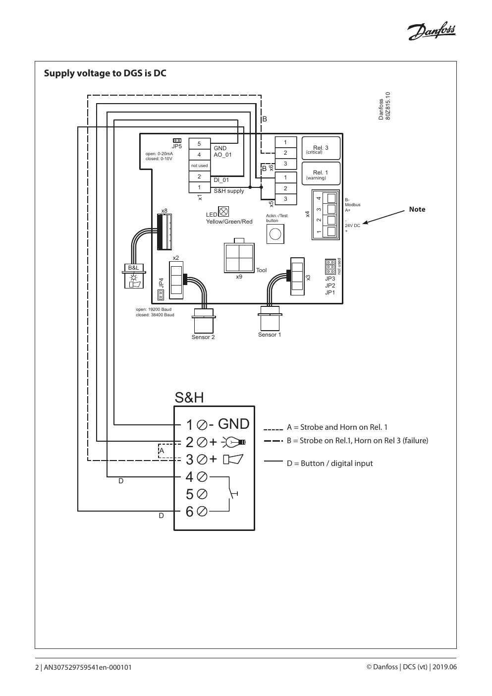
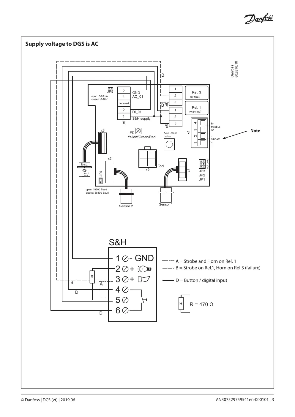
The Danfoss Gas Sensor Strobe and Horn is a visual and audible alarm device. Key installation requirements include using 16-24 AWG wire and ensuring the correct power supply configuration. If the Strobe and Horn is powered from the DGS and the DGS is powered by AC, a 470 ohm resistor must be installed.
Technical Specifications
- Operating Voltage: 9-28V DC
- Current Consumption: 9-35 mA (Siren) / 4-6 mA (Flash)
- IP Rating: IP 65
- Operating Temperature: -20 to +70 °C (-4.0 to +158 °F)
- Sound Output: 67-100 dB(A)
- Tones: 39 user-selectable tones
Installation and Wiring
The device features removable screw terminals. Wiring depends on whether the DGS supply voltage is DC or AC. Ensure the correct wiring diagram is followed based on your power source. A maximum of one Strobe and Horn unit may be connected to the DGS.
Tone Selection
The device supports 39 different tones. Use the DIP switches (1-6) to select the desired tone according to the provided tone selection table.
Volume Control
The volume can be adjusted by turning the control clockwise to increase loudness.
Manufacturer information
Danfoss A/S
Practical help
Common problems
Verify DIP switch settings (1-6) against the tone selection table on page 4.
Ensure the supplied 470 ohm resistor is installed when the S&H is powered from the DGS and the DGS is powered by AC.
Adjust the volume control clockwise.
Before use
- Verify supply voltage is 9-28V DC.
- Check if DGS power source is AC or DC.
- Ensure wire gauge is 16-24 AWG (0.25-1.50 mm²).
- Confirm tone selection DIP switch settings.
- Ensure no more than one Strobe and Horn unit is connected to the DGS.

Manual page author
Emily Carter
User documentation editor
Prepares concise manual descriptions and highlights the most useful setup, operation, and maintenance information for readers.