Installation Guide for Danfoss HRB and HFE Valve Coupling Accessories
Quick installation guide for Danfoss HRB and HFE valve coupling accessory kits (082G4235, 082G4230). Includes compatibility list and step-by-step mounting instructions for proper actuator alignment.
Table of contents
Manual images
Click an image to enlargeQuick guide from the manual
This document provides installation instructions for Danfoss coupling accessory kits 082G4235 and 082G4230, designed for HRB and HFE series valves. Proper installation requires identifying the correct kit for your specific valve model and following the positioning and assembly steps.
Compatibility and Kit Selection
Before installation, identify your valve model to select the correct accessory kit:
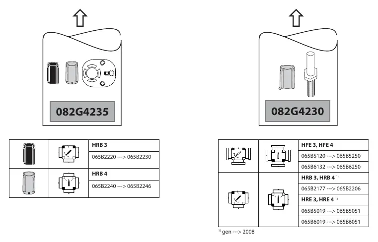
- Kit 082G4235: Compatible with HRB 3 and HRB 4 valves.
- Kit 082G4230: Compatible with HFE 3, HFE 4, HRB 3, HRB 4, HRE 3, and HRE 4 valves.
Installation Procedure
Follow these steps to install the coupling accessory:
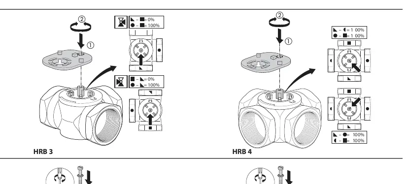
- Valve Positioning: Ensure the valve is set to the correct position (0% or 100%) as shown in the diagrams. This is critical for proper actuator alignment.
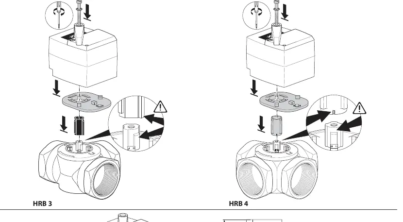
- Coupling Assembly: Align the coupling adapter with the valve stem. Ensure the orientation matches the valve type (HRB 3 vs HRB 4).
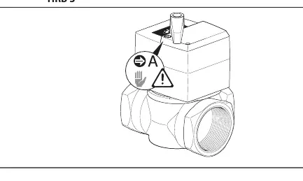
- Final Mounting: Secure the actuator onto the valve/coupling assembly. Verify that the actuator is seated correctly and the coupling is engaged.
Manufacturer information
Danfoss A/S
Practical help
Common problems
Verify your valve model (HRB 3, HRB 4, HFE 3, HFE 4, HRE 3, HRE 4) against the compatibility table on page 1 before starting.
Ensure the valve is correctly positioned at 0% or 100% before attempting to mount the coupling and actuator.
Before use
- Identify your valve model (HRB/HFE/HRE series).
- Select the correct accessory kit (082G4235 or 082G4230).
- Ensure the valve is in the correct position (0% or 100%) as indicated in the diagrams.

Manual page author
David Miller
Documentation analyst
Organizes user manual content into clear summaries, with attention to model details, product context, and everyday usability.