Installation Guide for Danfoss 148R9639 Gas Detection Service Tool
Quick installation guide for the Danfoss 148R9639 Gas Detection Service Tool. Includes wiring diagrams for Basic, Premium, Heavy Duty, and Controller expansion modules, plus an overview of software features like device addressing...
Table of contents
Quick Installation Guide
This document provides installation and connection instructions for the Danfoss Gas Detection Service Tool (148R9639). It is designed for configuring Basic, Premium, Heavy Duty, and Controller expansion modules.
Basic Installation Steps:
- Plug in the Service tool plug.
- Await the Display light to confirm connection.
- Follow the detailed instructions provided in the User Guide DKRCI.PS.S00.B1.02.
Wiring and Connections
The service tool connects to various modules using specific ports. Refer to the wiring diagrams for the following connections:
- Analog Output: Configurable via JP4 jumper (Open: 4-20mA, Closed: 2-10V).
- Digital Output: Connections for Horn and Flash light.
- Power Bus Comm: Connections for 24 VDC and GND.
- Field Bus: Connections for F_Bus_A and F_Bus_B.
Software Features
The service tool enables the following software capabilities for Basic, Premium, and Heavy Duty devices:
- Addressing of devices.
- Calibration of devices.
- Configuration of application parameters.
- Live monitoring of all measuring values.
Official resources from the manual
Manufacturer information
Danfoss A/S
Practical help
Before use
- Ensure the service tool plug is connected
- Wait for the display light to activate
- Verify the module type (Basic, Premium, Heavy Duty, or Controller expansion)
- Consult the full User Guide DKRCI.PS.S00.B1.02 for detailed configuration
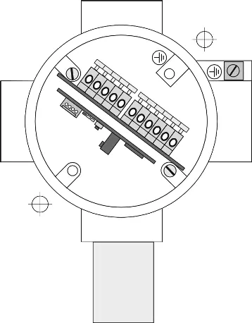
Images and diagrams
- The diagram shows connection points for various modules including X1, X2, X4, X8, X9, X10, X11, X12, and X13.
- Specific wiring for Analog Output, Digital Output, and Power Bus Comm is illustrated.

Manual page author
Emily Carter
User documentation editor
Prepares concise manual descriptions and highlights the most useful setup, operation, and maintenance information for readers.