Assembly Instructions for DucoGrille Classic 130HP Basic
A comprehensive assembly guide for the DucoGrille Classic 130HP Basic ventilation grille, covering component identification, frame construction, louvre installation, and bracing requirements.
Table of contents
Manual images
Jump to the sectionQuick guide from the manual
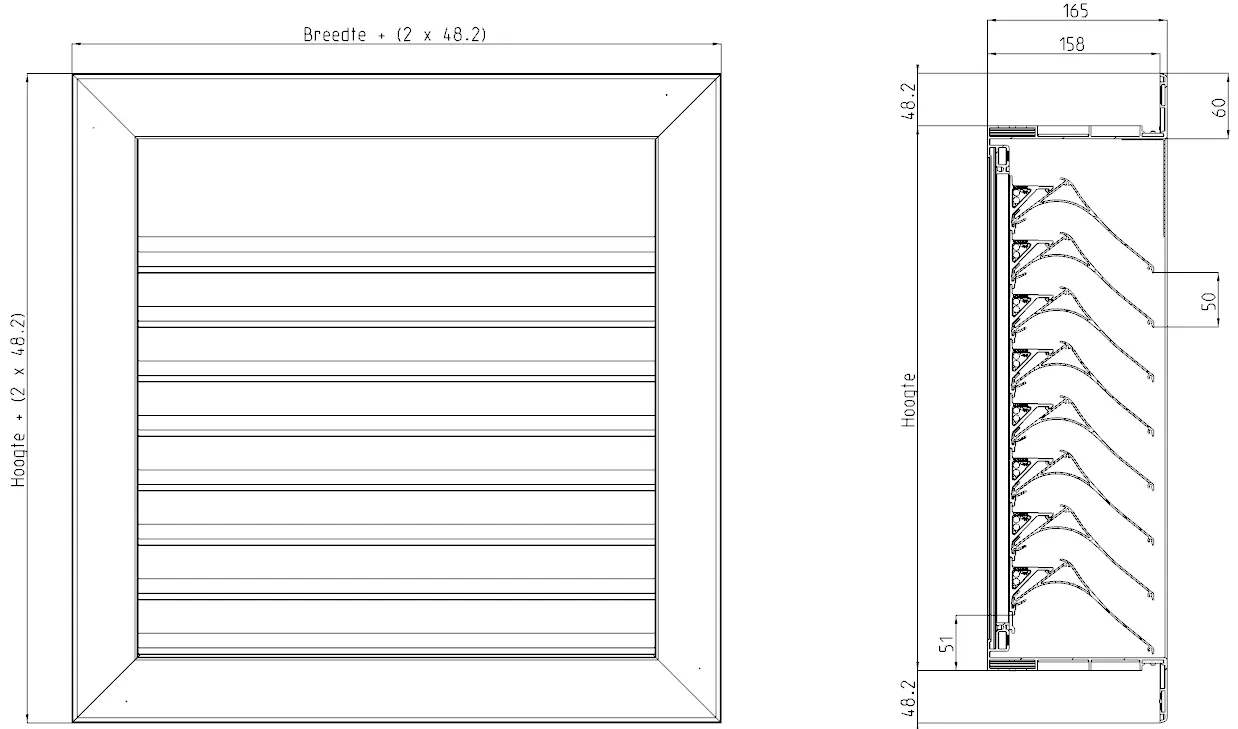
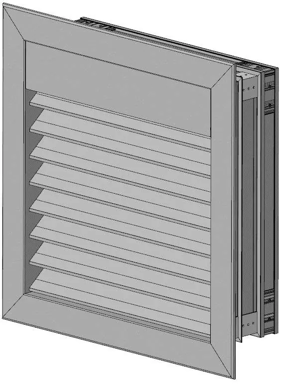
This document provides assembly instructions for the DucoGrille Classic 130HP Basic ventilation system. It covers both G-frame (flanged) and N-frame (flush-mounted) configurations. The assembly process involves preparing components, constructing the frame, installing louvre holders, and mounting the louvres. Intermediate bracing is required for units exceeding 800mm in width or height.
Components list
The system consists of various aluminum profiles, brackets, and fasteners. Key components include:
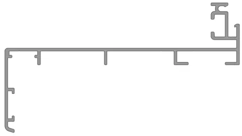
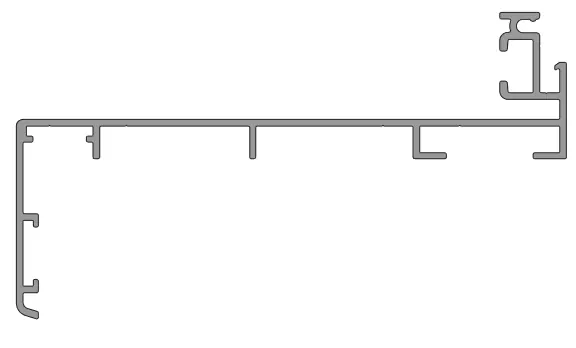
- Frame sections (G 130-150 or N 130-150)
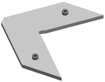
- Angle brackets (flat, small, large F50, 44, 46)
- Louvre holders (50HP) and end-pieces
- 130HP louvres
- Bracing sections (42/12) and T-shaped connecting pieces
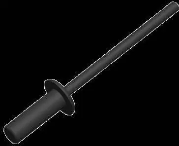
- Fasteners: Aluminum blind rivets (D4x12) and stainless steel self-drilling screws (3.5x13mm)
Assembly
Preparation: Generate the parts and cutting list using the calculation program. Ensure all parts are pre-painted. Mounting holes for painting must be made in the short lip of the L-section only. Use the sawing jig K0001553 for accurate mitre cuts.
Frame Construction:
- Drill drain holes in the bottom frame section (4mm bit, max 300mm spacing).
- Assemble the four frame sections using large F50 and small angle brackets.
- For G-flange frames, include flat angle brackets.
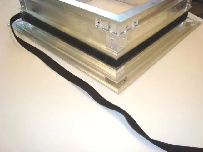
- Secure the framework with a belt until corners are tight.
- Use angle brackets 46 on all four corners, pre-drill with 4mm bit, and rivet.
- Release the belt and install angle brackets 44 on the bottom frame.
Louvre Installation:
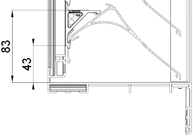
- Mount endpieces at 43mm and place 50HP clipholders 20mm above them (upside down compared to standard 50HP assembly).
- Clip in 130HP louvres, starting from the bottom and working upwards.
- Secure the top clip with a 3.5x13mm self-drilling screw.
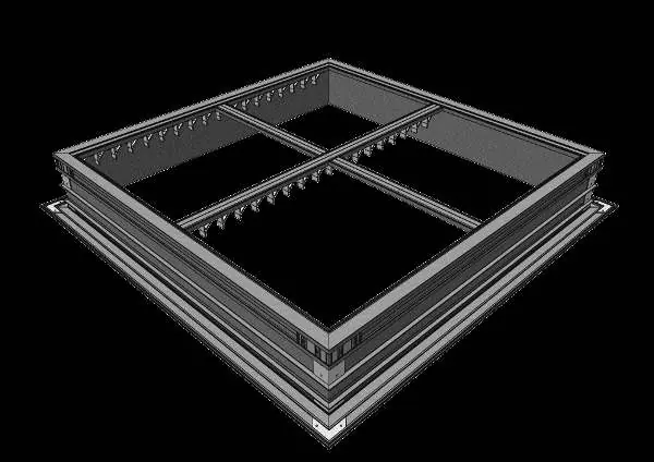
Bracing: For units over 800mm, install intermediate bracing. Use vertical bracing sections (42/12) with 50HP louvre holders, fastened with T-shaped connecting pieces and self-drilling screws.
Packaging
Standard louvres are supplied in HDPE blown film. Items larger than 700mm are bubble-wrapped. Each unit includes a label with the name, dimensions, colour, and barcode.
Manufacturer information
Duco Ventilation & Sun Control NV
Practical help
Common problems
Secure the framework using a belt until all openings are closed before riveting.
Ensure 50HP clipholders are placed upside down compared to a standard 50HP assembly.
Intermediate bracing is mandatory. Use vertical bracing sections (42/12) and T-shaped connecting pieces.
Before use
- Generate parts and cutting list via calculation program
- Ensure all parts are pre-painted
- Drill drain holes in the bottom frame section (4mm bit)
- Verify frame type (G-flange or N-flush)
- Check dimensions against calculation file
Specs in practice
- Minimum dimensions
- 250mm x 250mm
- Drain hole spacing
- Max 300mm between holes, 20mm from each end
Images and diagrams
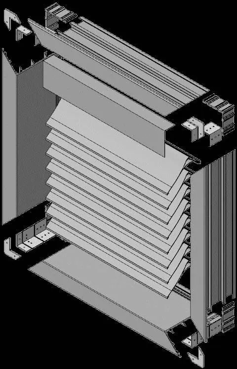
- Exploded view shows the assembly order of frame profiles and brackets.
- Step 5 illustrates correct drain hole drilling in the bottom profile.
- Step 12 shows the installation of intermediate bracing for large units.
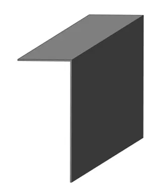
- Step 14-15 details the placement of the top L-section.
Model compatibility
- Assembly for N-frame (flush) is identical to G-frame, except flat angle brackets (G0009685) are not used.
- Intermediate bracing required if width or height exceeds 800mm.

Manual page author
Emily Carter
User documentation editor
Prepares concise manual descriptions and highlights the most useful setup, operation, and maintenance information for readers.