Parts Diagram for FLEX MT 18.0-EC Multitool
Access the official parts diagram and exploded view for the FLEX MT 18.0-EC cordless brushless multitool. Use this guide to identify components, assembly structure, and reference numbers for maintenance and repair.
Table of contents
Quick guide from the manual
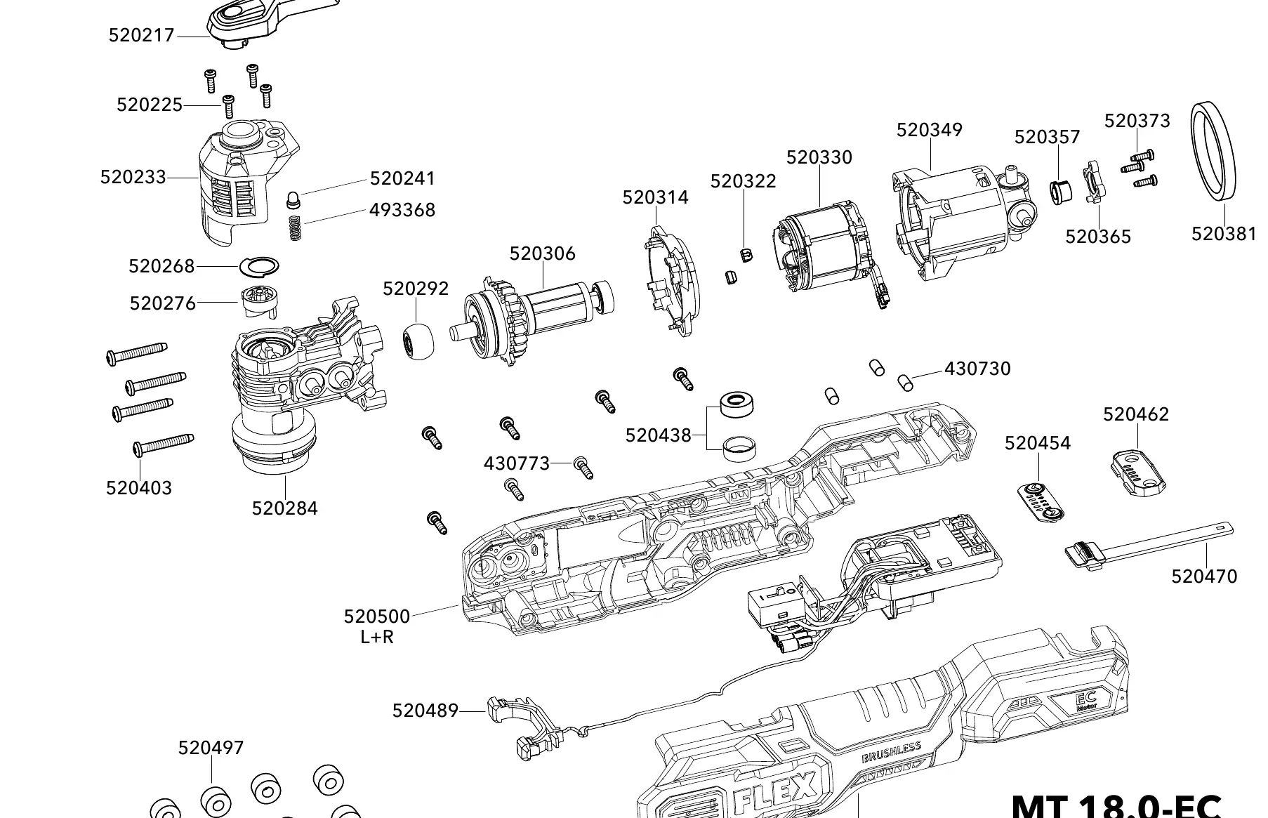
This document provides an official exploded view diagram for the FLEX MT 18.0-EC cordless brushless multitool. It is designed to assist users and technicians in identifying internal and external components, understanding the assembly structure, and locating specific part reference numbers for maintenance and repair purposes.
Parts Identification
The diagram illustrates the complete assembly of the MT 18.0-EC. Each component is marked with a specific reference number. These numbers correspond to the official FLEX parts catalog. When ordering replacement parts, ensure you reference the drawing number 520551 to guarantee compatibility with your specific tool version.
Maintenance and Assembly
The exploded view serves as a reference for the assembly sequence of the tool. When performing maintenance or repairs, refer to the relative positioning of parts shown in the diagram to ensure correct alignment and reassembly of the housing, motor, and internal mechanisms.
Manufacturer information
FLEX
Practical help
Common problems
Locate the part in the exploded view diagram and match it with the corresponding reference number. Use this number when contacting an authorized FLEX service center.
Before use
- Verify that the tool model is MT 18.0-EC.
- Ensure the drawing number matches 520551 for accurate part identification.
- Use the diagram to confirm the correct orientation of components during reassembly.

Manual page author
David Miller
Documentation analyst
Organizes user manual content into clear summaries, with attention to model details, product context, and everyday usability.