Parts Diagram for FLEX PD 2G 18.0-EC
Official parts diagram and exploded view for the FLEX PD 2G 18.0-EC cordless drill. Use this guide to identify components and part numbers for maintenance and repair.
Table of contents
Parts Diagram Overview
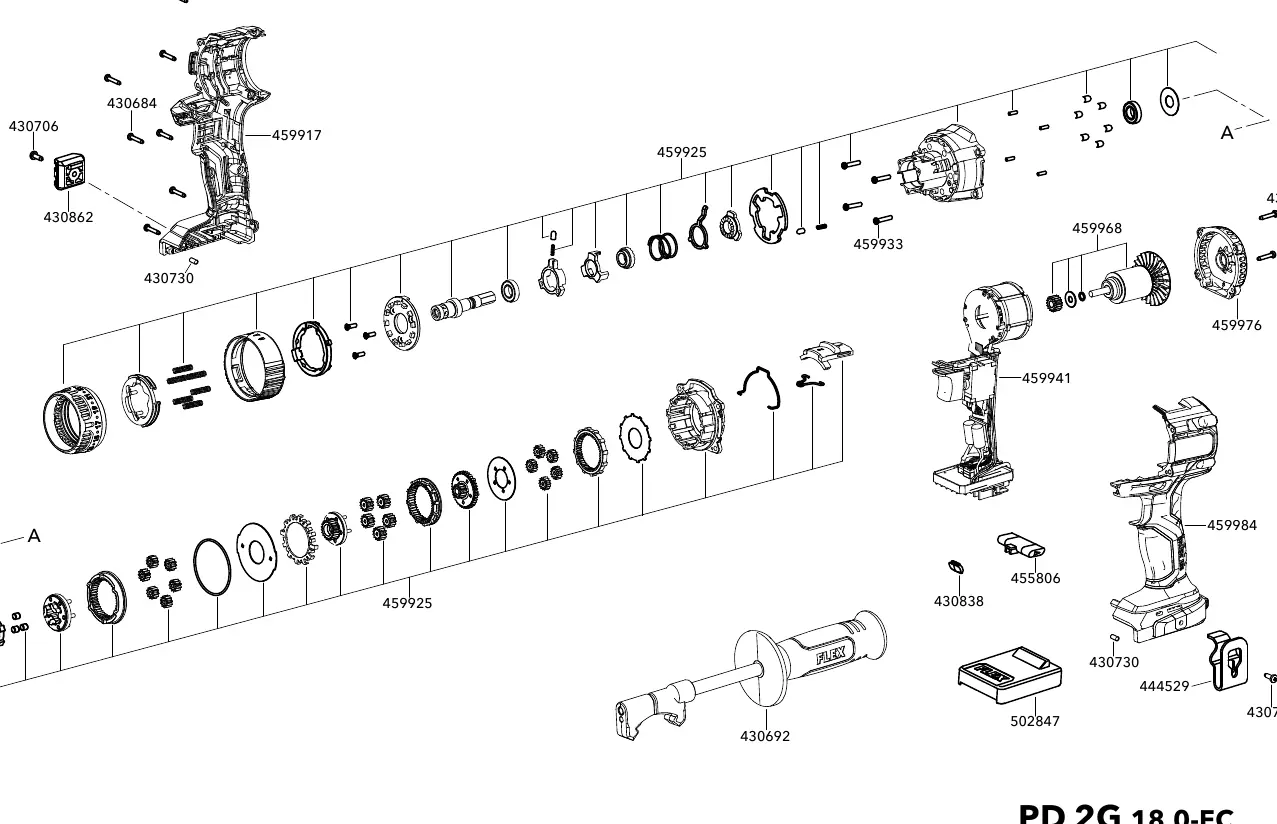
This document provides an official exploded view of the FLEX PD 2G 18.0-EC cordless drill. It is intended for service technicians and users looking to identify specific components for repair, maintenance, or replacement.
Using the Parts Diagram
The diagram displays the internal and external components of the tool. Each part is associated with a specific reference number. Use these numbers to locate the correct replacement parts through authorized FLEX service channels.
Component Identification
The exploded view illustrates the assembly order of the motor, housing, gearbox, and other internal mechanisms. Please refer to the diagram to understand the structural layout of the tool before attempting any disassembly or repair.
Warning: Disassembly of power tools should only be performed by qualified personnel. Improper assembly can lead to tool failure or safety hazards.
Manufacturer information
FLEX
Practical help
Before use
- Verify the model number matches your tool (PD 2G 18.0-EC).
- Ensure you have the correct tools for disassembly.
- Consult a professional if you are not experienced in power tool repair.
Images and diagrams
- The diagram shows the exploded view of the PD 2G 18.0-EC.
- Numbers in the diagram correspond to specific part identifiers.
- The drawing number is 462675.

Manual page author
Emily Carter
User documentation editor
Prepares concise manual descriptions and highlights the most useful setup, operation, and maintenance information for readers.