Parts List and Exploded View for FLEX XCE 8-150 18-EC
Access the official parts list and exploded view diagram for the FLEX XCE 8-150 18-EC angle grinder. Identify components and part numbers for maintenance and repair.
Table of contents
Quick Guide to the Parts Diagram
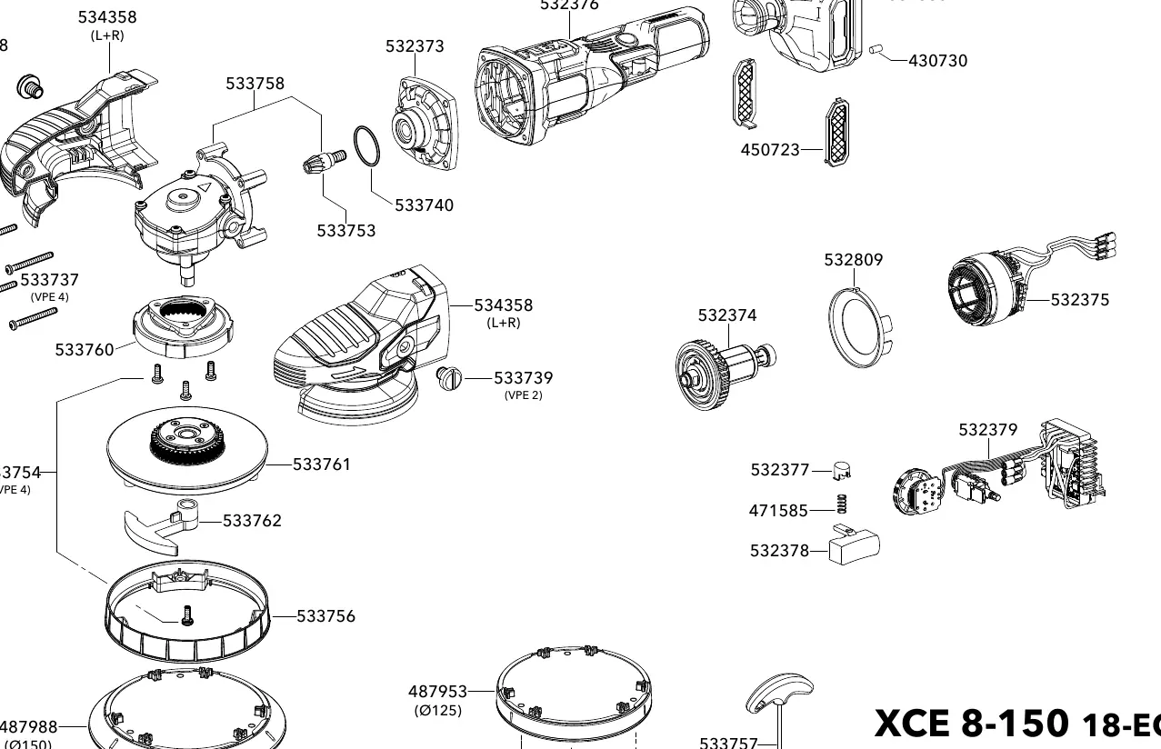
This document provides an official exploded view of the FLEX XCE 8-150 18-EC angle grinder. It is designed to assist users and technicians in identifying components, understanding the assembly structure, and locating specific part numbers for maintenance and repair.
Using the Exploded View
The diagram illustrates the assembly of the tool, showing the relationship between the gear head, motor housing, backing plate, and internal components. Each part is labeled with a specific reference number. When ordering replacement parts, ensure you reference the drawing number 534346 (dated 12-2025) to confirm compatibility with your specific tool version.
Maintenance and Repair
Before attempting any disassembly or repair, ensure the power source (battery) is disconnected from the tool. Use the exploded view to identify the correct orientation of parts during reassembly. If you are unsure about the repair process, contact an authorized service center for assistance.
Manufacturer information
FLEX
Practical help
Common problems
Locate the component on the exploded view diagram to find its corresponding reference number.
Use the drawing number 534346 and the specific part number from the diagram when contacting a service center.
Before use
- Ensure the battery is removed before performing any maintenance.
- Verify the tool model matches the XCE 8-150 18-EC.
- Use the diagram to identify the correct orientation of parts during reassembly.

Manual page author
David Miller
Documentation analyst
Organizes user manual content into clear summaries, with attention to model details, product context, and everyday usability.