Assembly Instructions for George Oliver 2012B Counter Height Bar Stool
Step-by-step assembly guide for the George Oliver 2012B counter height bar stool. Includes parts list, hardware requirements, and assembly sequence.
Quick answers from the manual
Quick answer
- The George Oliver 2012B bar stool is assembled by interlocking the legs, attaching the support ring with 6*30mm screws, mounting the swivel mechanism with 6*16mm screws, and finally attaching the seat with 6*16mm screws. p. 1
Key actions
- Assemble the leg base by interlocking B1 and B2. p. 1
- Attach the support ring (D) to the legs using 6*30mm screws (F). p. 1
- Attach the swivel mechanism (C) to the leg assembly using 6*16mm screws (E). p. 1
- Attach the seat (A) to the swivel mechanism using 6*16mm screws (E). p. 1
Where to find it in the PDF
- Assembly Instructions p. 1
Table of contents
Quick guide from the manual
This document provides the assembly instructions for the George Oliver 2012B counter height bar stool. Before beginning assembly, ensure all parts and hardware listed below are present. Use the provided Allen key for all screw installations.
Parts and Hardware
- A: Seat (x1)
- B1, B2: Legs (x1 set)
- C: Swivel mechanism (x1)
- D: Support ring (x1)
- F: 6*30mm screws (x4)
- E: 6*16mm screws (x8)
- H: Allen key
Assembly Instructions
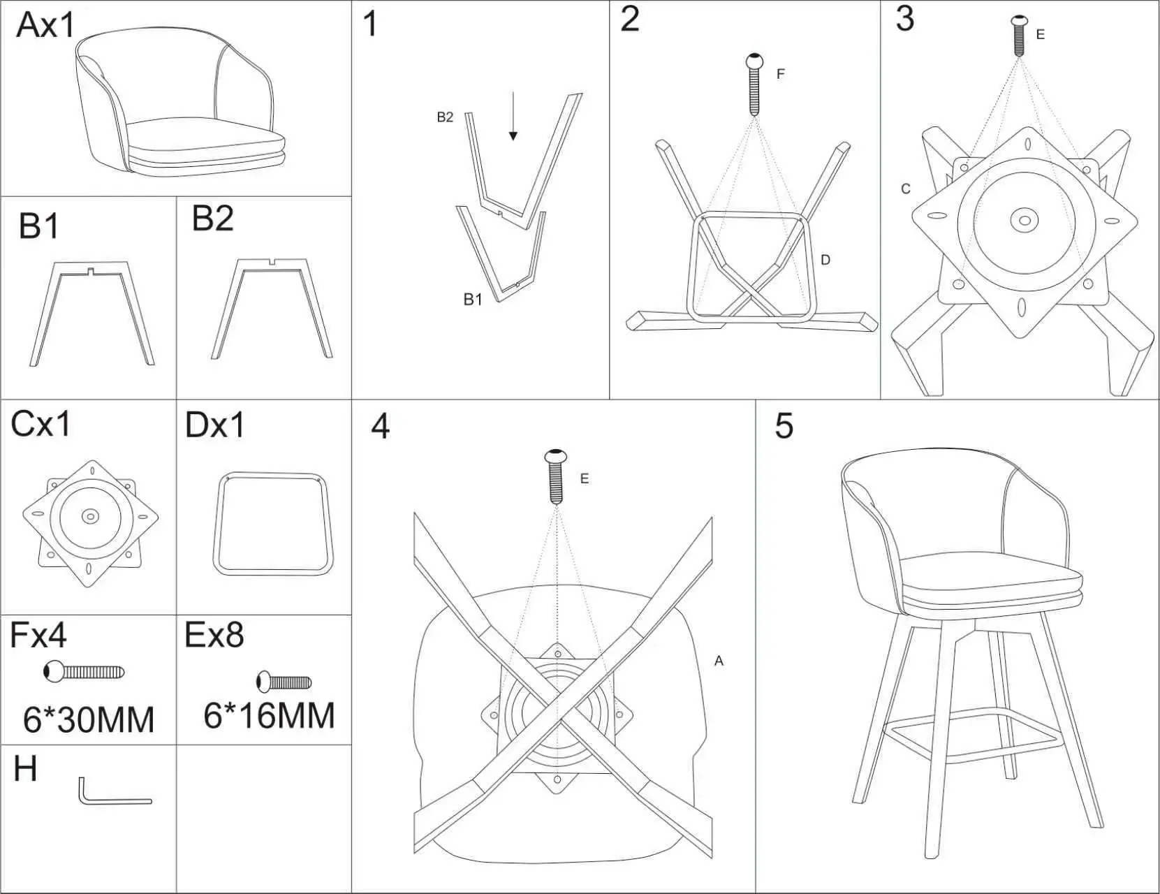
- Assemble Legs: Interlock the two leg pieces (B1 and B2) together.
- Attach Support Ring: Place the support ring (D) onto the assembled legs and secure it using the 6*30mm screws (F).
- Attach Swivel Mechanism: Position the swivel mechanism (C) on top of the leg assembly and secure it using the 6*16mm screws (E).
- Attach Seat: Place the seat (A) onto the swivel mechanism and secure it using the remaining 6*16mm screws (E).
- Final Check: Ensure all screws are tightened securely before use.
Practical help
Common problems
Ensure all screws (E and F) are tightened evenly. Check that the legs (B1 and B2) are properly interlocked.
Verify that the swivel mechanism (C) is not overtightened against the seat or leg assembly.
Before use
- Verify all parts (A, B1, B2, C, D) are present.
- Verify all hardware (F, E, H) is present.
- Ensure the Allen key (H) is used for all connections.
- Check that all screws are fully tightened after assembly.

Manual page author
David Miller
Documentation analyst
Organizes user manual content into clear summaries, with attention to model details, product context, and everyday usability.