Paradox Spectra 1728EX & 1738EX System Programming Guide
Comprehensive programming and configuration guide for Paradox Spectra 1728EX and 1738EX security systems, covering zone setup, system timers, communication settings, and module installation.
Table of contents
System Overview
The Paradox Spectra 1728EX and 1738EX are advanced security control panels designed for residential and commercial applications. This guide provides detailed instructions for system programming, including zone configuration, system timers, and communication settings to ensure reliable operation.
Getting Started
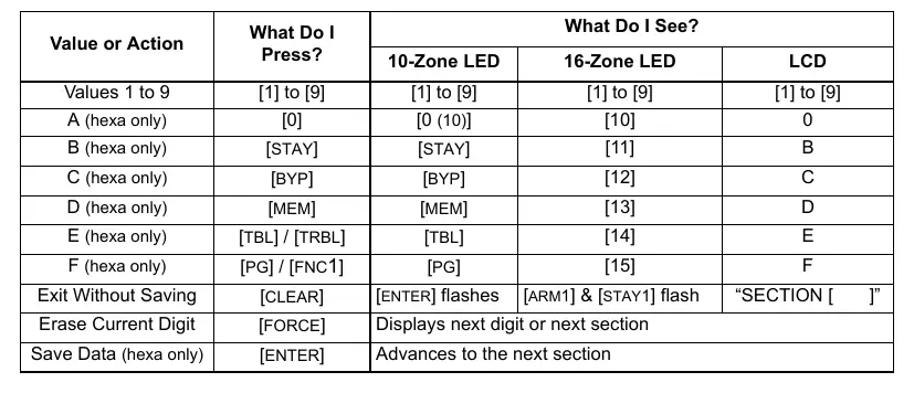
To enter programming mode, press the [ENTER] key, followed by your [INSTALLER CODE] (default: 000000). Once in programming mode, enter the 3-digit section number you wish to modify and input the required data. The system supports both decimal and hexadecimal data entry for flexible configuration.
Zone Programming
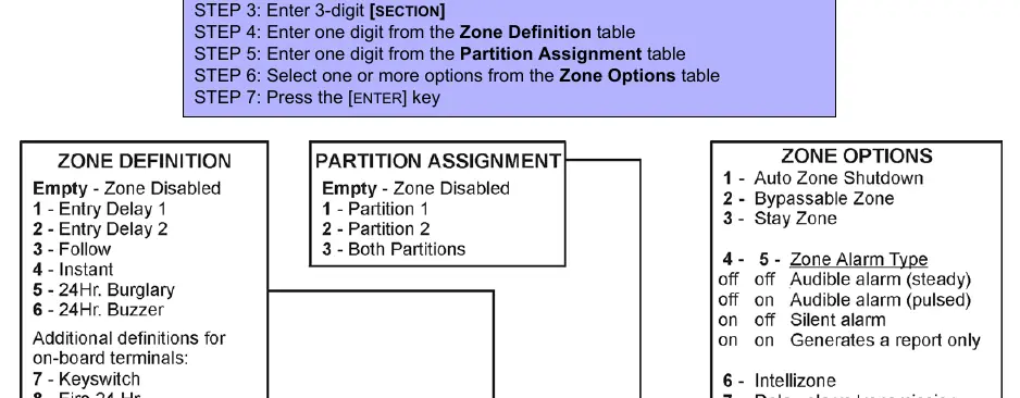
Zone assignments depend on the physical connection of detection devices to the control panel or expansion modules. Users can define zone types, partition assignments, and specific zone options such as auto-zone shutdown, bypassable zones, and alarm types. Ensure that inputs from different modules are not assigned to the same expansion input to avoid conflicts.
System Timers and Options
The system allows for precise control over various operational parameters, including zone speeds, entry/exit delays, and bell cut-off timers. General system options, such as partitioning, access code length, and panic key configurations, can be customized to meet specific security requirements.
Communication and Reporting
The control panel supports multiple reporting formats, including Ademco Contact ID, to communicate events to a central monitoring station. Users can configure event call directions, telephone numbers, and specific report codes for arming, disarming, alarms, and system troubles.
Hardware Connections and Maintenance
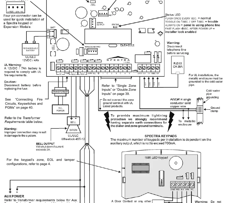
Proper hardware installation is critical for system reliability. The guide includes detailed PCB layouts for both the 1728EX and 1738EX models, illustrating connections for transformers, batteries, sirens, and keypads. Always disconnect AC power and battery before performing maintenance or adding modules to the communication bus. The system features a trouble display function to help identify and resolve issues such as low battery, power failure, or module faults.

Manual page author
Emily Carter
User documentation editor
Prepares concise manual descriptions and highlights the most useful setup, operation, and maintenance information for readers.