Installation Instructions for Resistex Doled TW LED Downlight
A quick installation guide for the Resistex Doled TW LED downlight. Includes wiring diagrams for tunable white control, cutout dimensions, and essential safety precautions.
Quick answers from the manual
Quick answer
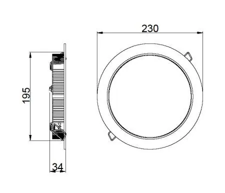
- The Resistex Doled TW is a tunable white LED downlight. Installation requires a 195mm ceiling cutout and connection to a compatible driver. p. 1, 2
Key actions
- Cut a 195mm hole in the ceiling. p. 2
- Connect wiring to the driver. p. 2
First start
- Ensure power is off, connect wires according to the diagram, and secure the fixture using spring clips. p. 2
Maintenance and reset
- Clean only with a dry cloth; do not use chemicals or abrasives. p. 1
Technical specifications
| Parameter | Value | Meaning | Pages |
|---|---|---|---|
| Cutout | 195mm | Required ceiling hole diameter | p. 1 |
Where to find it in the PDF
- Safety and Maintenance p. 1
- Installation and Wiring p. 2
Table of contents
Manual images
Click an image to enlargeQuick guide from the manual
This document provides installation instructions for the Resistex Doled TW LED downlight. It is intended for professional installers to ensure safe and correct operation.
Safety notes
- Never work on the luminaire while it is under voltage.
- Installation must be performed by a professional installer in compliance with electrical standards.
- Be aware of the risk of electrostatic discharges (ESD) and handle with precautions.
- Do not cover the fixture (non-recoverable).
Installation
The installation requires a ceiling cutout with a diameter of 195mm. The fixture is secured using spring clips.
Wiring
The fixture supports tunable white control. Connect the wires to the driver as follows:
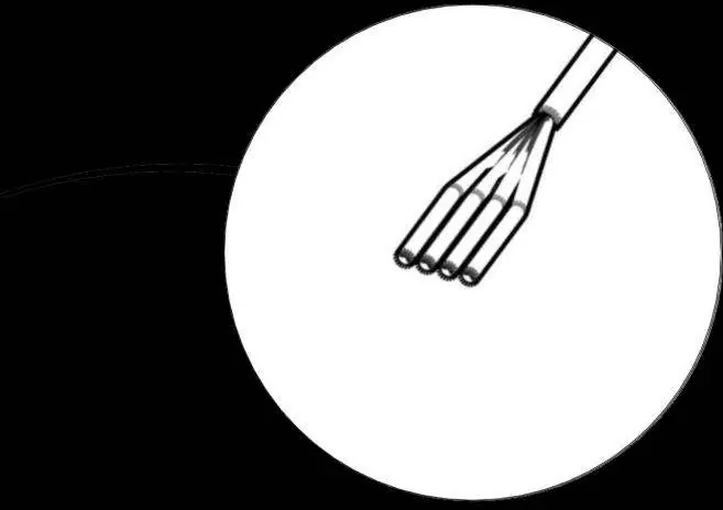
- White: Warm -
- Yellow: Warm +
- Black: Cool -
- Red: Cool +
The driver input terminals are marked: Com, Com, E, Switch, N, L.
Maintenance
Do not use chemicals or abrasive products to clean the fixture. Keep these instructions for future maintenance.
Practical help
Common problems
Check wiring connections (L, N, Switch) and ensure power is off during installation.
Verify wiring of Warm (White/Yellow) and Cool (Black/Red) channels.
Before use
- Ensure power is disconnected
- Verify cutout diameter is 195mm
- Confirm professional installer is available

Manual page author
Michael Turner
Technical manual editor
Reviews PDF manuals for structure, safety notes, and practical product details so readers can find the right information quickly.