Hvac / Thermostats Controls
Salus 091FLRFv2 Wireless Weekly Thermostat Operating Manual
Quick guide for the Salus 091FLRFv2 wireless weekly thermostat. Includes installation steps, pairing procedures, programming instructions, and technical specifications.
Table of contents
Manual images
Jump to the sectionQuick guide from the manual
The Salus 091FLRFv2 is a wireless weekly programmable thermostat designed for heating or cooling systems. The unit comes factory-paired with the RXRT510 receiver. Ensure installation is performed by a qualified professional. The thermostat requires 2x AA 1.5V alkaline batteries (do not use rechargeable batteries).
Installation
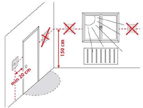
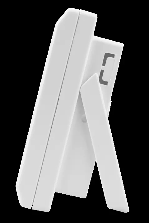
The thermostat should be mounted approximately 1.5m above floor level, away from heat sources, drafts, or direct sunlight. For wall mounting, use the provided template to drill holes. The device can also be used as a freestanding unit by unfolding the rear stand.
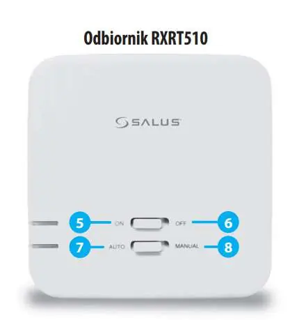
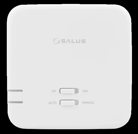
Receiver RXRT510
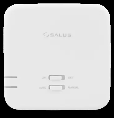
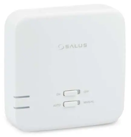
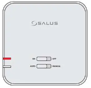
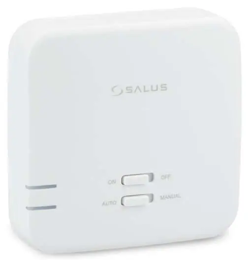
The receiver operates in two modes: AUTO (controlled by the thermostat) and MANUAL (controlled by switches on the receiver). For normal operation, set the switches to ON and AUTO. The receiver status is indicated by two LEDs: red (power/pairing) and green (heating signal).
Programming
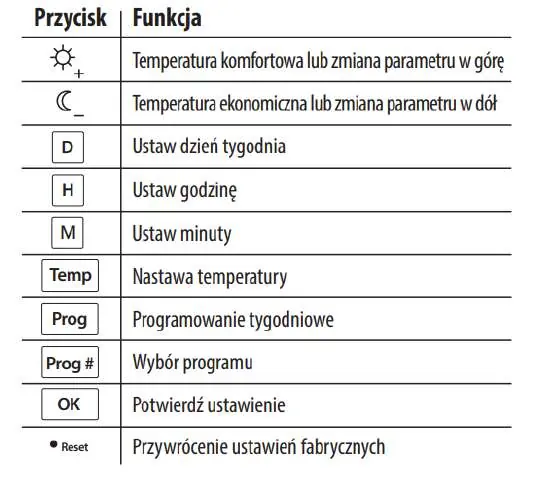
The thermostat offers 9 programs: 0-5 are factory-defined (non-editable), and 6-8 are user-definable. To set the time, use the D, H, and M buttons. To set comfort or economic temperatures, use the Temp button followed by the sun or moon icons. Programs can be assigned to specific days of the week using the Prog and Prog# buttons.
Service Menu
To access advanced settings, hold the OK button for 5 seconds. Parameters include: heating/cooling mode, delay start (5 min), hysteresis (0.5°C or 1.0°C), temperature offset, relay output type, and pairing (SYNC).
Pairing
If communication is lost or a new receiver is added, use the SYNC function in the service menu. Ensure the receiver is in pairing mode (red LED flashing) before initiating the process on the thermostat.
Maintenance and Troubleshooting
Clean the device with a soft, damp cloth. Do not use abrasive cleaners or solvents. If the thermostat does not respond, a factory reset can be performed using the small hole next to the OK button (use a paperclip, not a pencil). If the red LED on the receiver continues to flash after 10 minutes, check for obstacles or interference between the devices.

Manufacturer information
SALUS Controls
Practical help
Common problems
Receiver red LED flashing
Indicates standby mode (no signal for 1 hour), pairing mode, or lost connection. Check battery levels in the thermostat and ensure it is within range.
Thermostat not controlling heating
Verify receiver switches are set to ON and AUTO. Test radio transmission by setting a higher target temperature and checking for the antenna symbol.
Reset button not working or damaging device
Do not use a pencil to press the reset button; graphite can cause a short circuit. Use a paperclip.
Before use
- Install 2x AA 1.5V alkaline batteries in the thermostat.
- Ensure receiver is connected to 230V AC power.
- Set receiver switches to ON and AUTO positions.
- Verify thermostat and receiver are within 60m range.
- Check that the installation location is free from metal obstacles or thick walls.
Specs in practice
- Hysteresis (SPAN)
- The temperature difference (0.5°C or 1.0°C) that triggers the heating/cooling cycle.
- Max relay load
- 16A for resistive loads, 5A for inductive loads.
- Protection class
- IP30 rating; keep away from water and moisture.
Images and diagrams
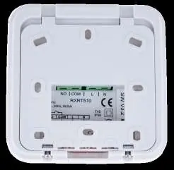
- The receiver wiring diagram shows connections for L (Live), N (Neutral), COM (Common), and NO (Normally Open) terminals.
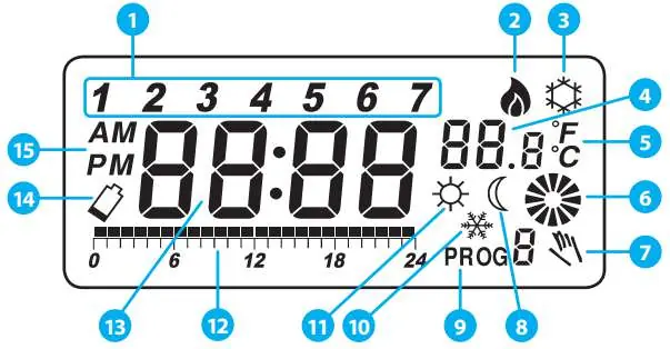
- The thermostat display icons indicate the day of the week, heating/cooling mode, current/target temperature, and program status.
Model compatibility
- Compatible with gas boilers, oil boilers, and heat pumps.
- Relay output type (NO/NC) can be configured in the service menu (available from software ver. 2.6).

Manual page author
Emily Carter
User documentation editor
Prepares concise manual descriptions and highlights the most useful setup, operation, and maintenance information for readers.