Installation Guide for Sauermann Omega Pack 2 Condensate Pump
Quick installation and wiring guide for the Sauermann Omega Pack 2 condensate pump, including detailed wiring diagrams for Split, Multisplit, and VRF air conditioning systems.
Quick answers from the manual
Quick answer
- The Sauermann Omega Pack 2 is a condensate pump designed for air conditioning systems. This document provides the necessary wiring diagrams for connecting the pump to Split, Multisplit, and VRF systems. p. 1, 2
Key actions
- Connect the pump according to the wiring diagram specific to your system type (Split/Multisplit or VRF). p. 1, 2
Technical specifications
| Parameter | Value | Meaning | Pages |
|---|---|---|---|
| Power Supply | 230V ~ 50Hz | Operating voltage and frequency | p. 1, 2 |
| Safety Switch | NC 3A resistive load - 250V | Maximum resistive load for the safety switch | p. 1, 2 |
Show 1 more answers Show less
Where to find it in the PDF
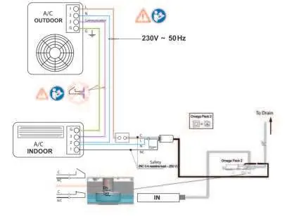
- Split & Multisplit System Wiring p. 1
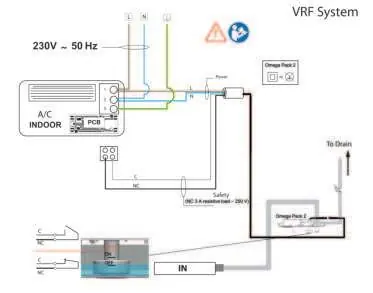
- VRF System Wiring p. 2
Table of contents
Manual images
Click an image to enlargeQuick guide from the manual
This document provides essential wiring diagrams for the installation of the Sauermann Omega Pack 2 condensate pump. It covers two primary configurations: Split/Multisplit systems and VRF systems. Ensure all electrical connections are made according to the specific system type to ensure proper operation and safety.
Wiring for Split & Multisplit Systems
The wiring diagram for Split and Multisplit systems illustrates the connection between the A/C Outdoor unit, A/C Indoor unit, and the Omega Pack 2 pump. Ensure the power supply is 230V ~ 50Hz. The safety switch is rated for an NC 3A resistive load at 250V.
Wiring for VRF Systems
The wiring diagram for VRF systems details the specific connections required for this configuration. As with the Split system, the power supply requirement is 230V ~ 50Hz, and the safety switch specifications remain consistent.
Manufacturer information
Sauermann
Practical help
Common problems
Verify that the wiring connections match the schematic for your specific system type (Split/Multisplit or VRF) and that the power supply is active.
Before use
- Verify power supply is 230V ~ 50Hz.
- Identify if the system is Split/Multisplit or VRF.
- Ensure correct wiring of the safety switch (NC 3A resistive load - 250V).

Manual page author
Michael Turner
Technical manual editor