Industrial / Electrical
Schneider 140CRA93100 RIO Drop Adaptor Module Instruction Manual
Comprehensive installation, configuration, and maintenance guide for the Schneider 140CRA93100 RIO Drop Adaptor Module, covering network topologies, cabling, grounding, and optical fiber integration.
Table of contents
Product Overview
The 140CRA93100 RIO Drop Adaptor is a key component in the Quantum RIO network, which functions as a single-master system. The RIO processor (140CRP93x00) acts as the master node, while RIO adapters facilitate communication with various drops. A single network can support up to 31 drops, each requiring a unique address set via rotary switches on the rear panel.
Network Topologies and Cabling
RIO networks rely on precisely defined topologies, including single, dual, and redundant cable systems. Illegal configurations can lead to network dysfunction. Key components include:
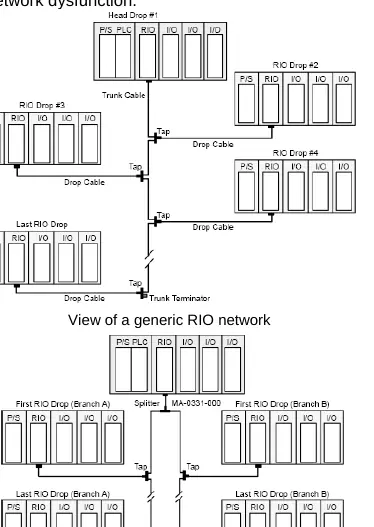
- Trunk Cables: RG-11 (97-5951-000) is recommended for the main network backbone.
- Drop Cables: RG-6 (97-5750-000) is used to connect taps to adapters.
- Taps (MA-0185-100): Used to isolate drop adapters and prevent interference.
- Splitters (MA-0331-000): Used to create branches in the trunk; only one is permitted per network.
Proper impedance matching is critical. All components have a characteristic impedance of 75 Ohms. Unused ports must be terminated with dedicated 75 Ohm terminators (e.g., 52-0422-000 for trunk ports, 52-0402-000 for drop ports).
Installation and Safety
To avoid signal disturbances, adhere to strict length requirements: minimum drop cable length is 2.5m, and maximum is 50m. Taps must be installed at least 2.5m apart. Never connect or disconnect cables on an active network to prevent communication errors and equipment damage.
Grounding and Electromagnetic Interference
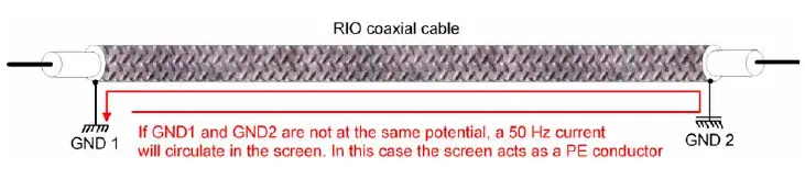
The cable system must be grounded at exactly one point within 6m of the RIO processor. Avoid routing RIO cables near AC/DC power lines. If cables must cross power lines, they should do so at right angles. In high-noise environments, use steel conduit. For harsh electromagnetic conditions, optical fiber media is recommended to provide electrical isolation.
Optical Fiber Repeaters
490NRP95400 Optical Fiber Repeaters allow for transitions between coaxial and fiber media. When using these, the NRP chassis must be grounded, and the jumper switch must be set correctly based on whether the unit acts as a drop or a head. Always power off the network before installing or replacing repeaters.
Commissioning and Maintenance
Post-installation, perform Time-Domain Reflectometer (TDR) measurements to verify the copper network's integrity and ensure total attenuation does not exceed 35dB. For fiber networks, use an optical power loss kit to ensure attenuation remains within the 11dB budget. Regularly verify grounding and inspect for physical damage to cables, as bending beyond the specified radius can cause signal reflections and transmission errors.
Related manuals
Related manuals from the same brand or category.