Senva EMX True RMS Energy Meter Modbus Communications Guide
Comprehensive guide for configuring and communicating with the Senva EMX energy meter via Modbus protocol, including register maps, setup parameters, and data conversion methods.
Table of contents
Product Overview
The Senva EMX is a high-precision True RMS energy meter designed for advanced power monitoring. This guide provides detailed instructions for integrating the device into a Modbus network, allowing for remote configuration, real-time data acquisition, and energy logging.
Setup and Configuration
The EMX meter features an intuitive OLED display for local configuration. Users can navigate menus using the ENTER, ESC, UP, and DOWN buttons to adjust critical parameters such as phase configuration, current element type, and scaling factors. All settings are stored in non-volatile memory, ensuring data retention during power loss.
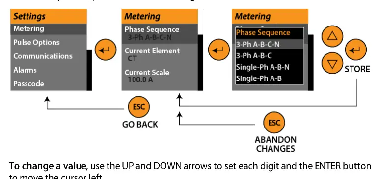
Key Parameters
- Metering: Configure voltage and current scaling, phase sequencing, and display units.
- Pulse Output: Customize pulse source, duration, and energy units for external integration.
- Communications: Set protocol (Modbus/BACnet), baud rate, parity, and slave address.
- Alarms: Enable and define thresholds for voltage, current, frequency, and power factor out-of-range conditions.
- Advanced: Access firmware versions and perform factory resets.
Modbus Communications
The EMX supports standard Modbus RTU communication. The device acts as a Modbus client (slave) with a default address of 247. Supported function codes include 0x03 (Read Holding Registers), 0x04 (Read Input Register), 0x06 (Write Single Register), and 0x10 (Write Multiple Registers).
Data Handling
The meter provides extensive registers for power, energy, and status monitoring. Users must apply specific scale factors to raw register values to obtain accurate readings. For 32-bit and 64-bit data, the device utilizes consecutive 16-bit registers that must be merged by the host software. Detailed conversion formulas are provided for U16 to I16, U32, U64, and I64 data types to ensure accurate interpretation of energy accumulators.
Logging and Maintenance
Models with firmware 2.0 or greater support internal data logging. Users can define up to 12 log sources, set trigger intervals, and select between continuous or one-shot logging modes. The device also maintains real-time clock registers for accurate time-stamping of logged events. Regular maintenance involves monitoring alarm status bitfields and ensuring that communication parameters are correctly synchronized with the host system.