Installation and Operation Instructions for Skytech 1001D-A Remote Control System
Quick guide for the Skytech 1001D-A remote control system for gas heating appliances. Includes installation steps, battery replacement, wiring instructions, and troubleshooting.
Table of contents
Quick guide from the manual
The Skytech 1001D-A is a remote control system designed for gas heating appliances with millivolt gas valves. It consists of a wall-mounted transmitter and a receiver. The system must be installed by a qualified electrician. Important: This product is for attended hearth appliances only; never leave the appliance burning unattended.
Installing and replacing batteries
Transmitter: Uses (2) 3-volt button cell batteries. Remove the faceplate with a small screwdriver, insert batteries with the (+) side facing up, and snap the faceplate back on.
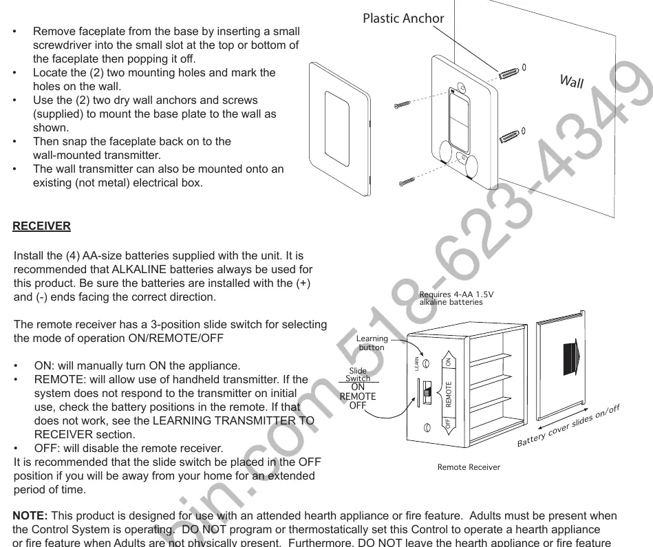
Receiver: Uses (4) AA alkaline batteries. Ensure correct polarity (+/-) as indicated in the battery holder.
Wall mounting the transmitter
Remove the faceplate, mark the two mounting holes on the wall, use the supplied dry wall anchors and screws to mount the base, and snap the faceplate back on. It can also be mounted on an existing non-metal electrical box.
Mounting the remote receiver
The receiver should be wall-mounted in a plastic switch box (not metal) to protect it from heat, or placed near the hearth. Keep away from temperatures exceeding 130°F. If wall-mounting, use 18 AWG wires (not included, max 20 feet). Ensure the receiver slide switch is in the OFF position during installation.
Wiring instructions
Millivolt Gas Valves: Connect one wire from the receiver to the TH terminal and the other to the TH/TP terminal on the gas valve.
Electronic Spark Ignition Systems: Connect in series to a 24VAC transformer. Connect the hot wire from the transformer to one receiver terminal, and the other receiver terminal to the TH (thermostat) terminal on the electronic module.
Learning transmitter to receiver
To pair the transmitter, set the receiver slide switch to REMOTE. Use a small screwdriver or paperclip to press the black LEARN button inside the hole on the receiver face. The receiver will beep. Within 2 seconds, press the ON or OFF button on the transmitter. The receiver will emit several beeps to confirm pairing.
Troubleshooting
If the system fails to operate, check that batteries are fresh and correctly installed. Ensure the receiver is within 20-25 feet of the transmitter. If the receiver is in a metal enclosure, range will be reduced. Verify that the receiver slide switch is set to REMOTE.
Practical help
Common problems
Check battery orientation and charge. Ensure receiver slide switch is in REMOTE position. Perform the 'Learning' procedure again.
Check battery levels. Ensure receiver is not in a tightly enclosed metal surrounding and is within 20-25 feet of the transmitter.
Batteries may be dead or installed incorrectly. Ensure (+) and (-) ends are facing the correct direction.
Before use
- Ensure all batteries are fresh and installed with correct polarity.
- Verify receiver slide switch is in the REMOTE position for normal operation.
- Confirm the appliance is attended by an adult while in operation.
- Check that all wiring connections are secure and follow manufacturer specifications.
- Ensure the receiver is kept away from temperatures exceeding 130°F.
Specs in practice
- Operating Range
- 20 to 25 feet for optimal communication.
- Temperature Limit
- Do not expose receiver or batteries to temperatures above 130°F to prevent damage and shortened battery life.
Images and diagrams
- Transmitter: Shows battery insertion and faceplate removal using a small screwdriver.
- Receiver: Illustrates the 3-position slide switch (ON/REMOTE/OFF) and the LEARN button location.
- Wiring: Provides schematics for connecting to millivolt gas valves and electronic spark ignition modules.
Model compatibility
- Designed for use with millivolt gas valves.
- Compatible with electronic spark ignition systems using a 24VAC transformer.
- Receiver must be mounted in a plastic (non-metal) switch box.

Manual page author
Michael Turner
Technical manual editor
Reviews PDF manuals for structure, safety notes, and practical product details so readers can find the right information quickly.