Lighting / Decorative Lighting
Installation Guide for Solight 1MK22 TV Wall Mount
A comprehensive installation guide for the Solight 1MK22 TV wall mount. Includes a detailed parts list, step-by-step mounting instructions, and technical specifications for VESA compatibility and tilt adjustment.
Quick answers from the manual
Quick answer
- The Solight 1MK22 is a TV wall mount supporting VESA 400x400. Installation involves attaching the TV plate, drilling 8mm holes in the wall, securing the wall plate with anchors, and adjusting the tilt angle via the adjustment knob. p. 1, 2
Key actions
- Drill holes for wall plate p. 1
- Adjust tilt angle p. 2
Technical specifications
| Parameter | Value | Meaning | Pages |
|---|---|---|---|
| Max VESA | 400x400 | Maximum mounting hole pattern | p. 1 |
| Tilt | -20 to +20 degrees | Vertical tilt adjustment range | p. 1 |
Where to find it in the PDF
- Installation Steps 1-5 p. 1
- Installation Steps 6-7 p. 2
Table of contents
Manual images
Click an image to enlargeQuick guide from the manual
The Solight 1MK22 is a TV wall mount designed for flat installation. Before beginning, ensure your TV is compatible with the VESA 400x400 standard. The mount allows for a vertical tilt adjustment of -20 to +20 degrees.
Parts List
Before starting, verify that all components are present in the package:
- Screws: M6x60 (A), M4x14 (I), M5x30 (J), M6x14 (K), M6x30 (L), M8x20 (M), M8x30 (N), M6x12 (O)
- Hardware: 8x40 Plastic Anchors (B), M6x16 Flat washers (C), M8x16 Flat washers (D), 5mm Plastic Sleeves (E, F), M6 Cap nut (P)
Installation Instructions
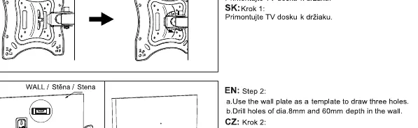
- Install the TV plate: Attach the TV plate to the back of your television using the appropriate screws from the parts list.
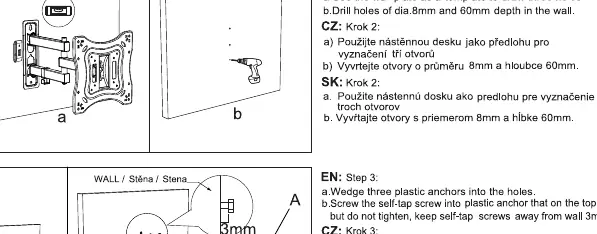
- Prepare the wall: Use the wall plate as a template to mark and drill three holes. Use an 8mm drill bit to a depth of 60mm.
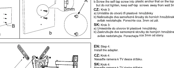
- Insert anchors: Insert the three plastic anchors into the drilled holes. Screw the self-tap screws into the anchors, but do not tighten fully; leave approximately 3mm of space from the wall.
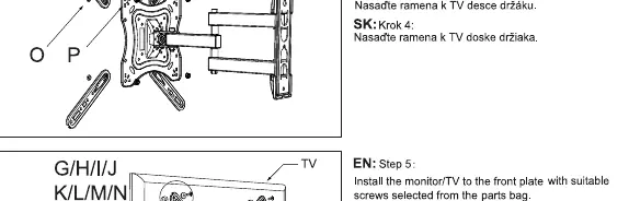
- Install the adapter: Attach the adapter arms to the TV plate.
- Mount the TV: Secure the TV with the attached adapter arms onto the wall plate.
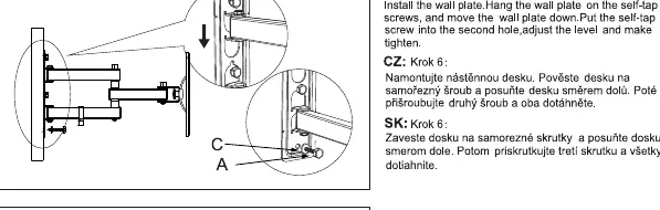
- Secure the wall plate: Hang the wall plate on the self-tap screws, slide it down to lock into position, insert the second screw, adjust the level, and tighten all screws firmly.
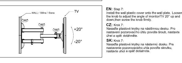
- Final adjustment: Install the plastic cover. To adjust the tilt angle, loosen the knob, set the desired angle, and tighten the knob firmly.
Technical Specifications
- VESA Compatibility: Up to 400x400mm
- Tilt Range: -20 to +20 degrees
Practical help
Common problems
TV is not level after mounting
Loosen the wall plate screws slightly, adjust the level of the plate, and re-tighten the screws.
Tilt adjustment is too loose or too stiff
Adjust the tension of the knob on the mount to achieve the desired resistance.
Before use
- Verify all parts listed in the manual are present.
- Ensure the wall structure is capable of supporting the TV and mount.
- Check that the TV mounting holes match the VESA 400x400 standard.
- Use an 8mm drill bit for wall holes.
- Ensure wall holes are drilled to a depth of 60mm.
Specs in practice
- VESA 400x400
- The maximum distance between mounting holes on the back of the TV is 400mm horizontally and 400mm vertically.
- Tilt -20 to +20 degrees
- The mount allows the TV to be tilted downwards by 20 degrees or upwards by 20 degrees.
Images and diagrams
- The manual provides visual steps for drilling, anchoring, and attaching the TV plate.
- Step 6 illustrates how to hang the wall plate on the pre-installed screws and lock it into place.
Model compatibility
- Compatible with VESA patterns up to 400x400.

Manual page author
Michael Turner
Technical manual editor
Reviews PDF manuals for structure, safety notes, and practical product details so readers can find the right information quickly.