Computers / Storage
User Manual for Supermicro SuperServer 1017R-WR
A comprehensive user guide for the Supermicro SuperServer 1017R-WR. This manual covers server installation, motherboard setup, BIOS configuration, system maintenance, and troubleshooting.
Table of contents
Manual images
Click an image to enlargeQuick Guide
The SuperServer 1017R-WR is a 1U rackmount server based on the SC514-R400W chassis and the X9SRW-F motherboard. This manual is intended for professional system integrators and technicians. Always ensure the system is powered down and disconnected from power sources before performing hardware maintenance.
Server Installation
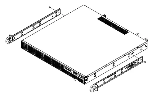
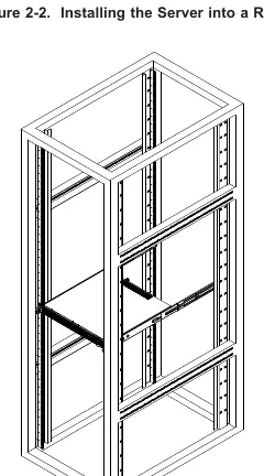
Before installing the server into a rack, ensure the location is clean, dust-free, and well-ventilated. Maintain approximately 25 inches of clearance in the front and 30 inches in the back for airflow and servicing. Install the heaviest components at the bottom of the rack first. Use the provided rail kit to secure the server.
System Interface
The front control panel includes a power button, reset button, and several status LEDs. The Universal Information LED indicates system health: fast blinking red for fan failure, slow blinking red for power failure, and solid red for CPU overheat. Blue indicates the Unit Identifier (UID) is active.
Motherboard Setup
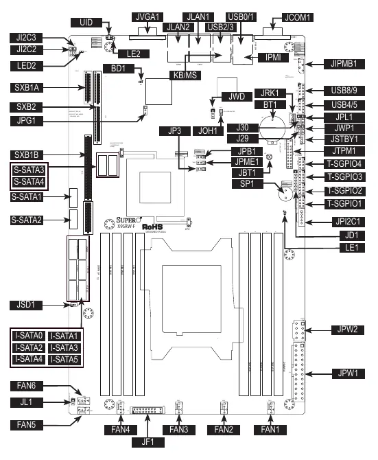
The X9SRW-F motherboard supports a single Intel Xeon E5-2600/E5-1600 series processor (LGA2011). When installing the CPU, ensure it is aligned correctly with the socket keys. Memory should be installed in the DIMM slots starting with DIMM1A. Use DDR3 DIMM modules of the same size, type, and speed for optimal performance. The board features various jumpers for configuration, such as CMOS clear (JBT1) and VGA enable/disable (JPG1).
Chassis Setup
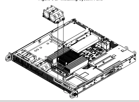
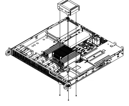
The chassis features four 4-cm counter-rotating fans. If a fan fails, the remaining fan will ramp up to full speed. To replace a fan, power down the system, remove the chassis cover, and swap the failed unit with an identical 4-cm, 12V fan. The chassis supports two internal 2.5-inch SATA hard drives in a removable bracket.
BIOS Configuration
Access the BIOS Setup Utility by pressing the Delete key during system boot. The BIOS allows configuration of CPU settings, memory, SATA/SAS ports, and server management features. Use the arrow keys to navigate and the provided hotkeys to save changes or restore defaults.
Troubleshooting
The system uses audible beep codes to indicate fatal errors during POST. 1 beep indicates a successful refresh/reset. 5 short beeps plus 1 long beep indicates a memory error. 5 beeps indicate a display memory read/write error. If the OH LED is on, the system is overheating.
Specifications
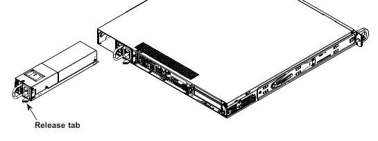
The system supports up to 512GB of ECC LRDIMM memory. It includes a redundant 400W power supply with auto-switching (100-240V AC). Operating temperature is 10 to 35 degrees Celsius.
Manufacturer information
Super Micro Computer, Inc.
Practical help
Common problems
System fails to boot
Check BIOS beep codes. 5 short beeps + 1 long beep indicates a memory error; 5 beeps indicate a video adapter or memory issue.
Overheat LED is on
Check for cable obstructions, ensure all fans are operating, and verify heatsinks are properly installed.
Fan failure
Replace the failed fan with an identical 4-cm, 12V fan. The system can continue to run with a failed fan, but it should be replaced promptly.
Before use
- Ensure the rack is stable and leveled.
- Verify CPU and memory are correctly installed.
- Connect power cables to both power supply modules.
- Ensure proper airflow clearance (25 inches front, 30 inches back).
- Verify all chassis covers are installed for proper cooling.
Specs in practice
- Memory Capacity
- Supports up to 512GB ECC LRDIMM, 256GB ECC RDIMM, or 64GB ECC/non-ECC UDIMM.
- Power Supply
- Redundant 400W hot-plug power supply modules.
Images and diagrams
- Front Control Panel: Identifies buttons and LED indicators for system status.
- Motherboard Layout: Shows locations of CPU, memory slots, jumpers, and connectors.
- BIOS Setup: Navigation guide using arrow keys and hotkeys.
Model compatibility
- Requires Intel-certified multi-directional heatsink.
- Enterprise-level hard drives are recommended.
- Requires IPMI-compatible Management Engine firmware for IPNM features.

Manual page author
David Miller
Documentation analyst
Organizes user manual content into clear summaries, with attention to model details, product context, and everyday usability.