Instruction Manual for Taco 0034e High-Efficiency Circulator
Quick guide for the Taco 0034e circulator, covering installation, wiring, operating modes, dial settings, and troubleshooting error codes.
Table of contents
Manual images
Jump to the sectionQuick guide from the manual
The Taco 0034e is a high-performance, variable-speed, wet-rotor circulator with an ECM permanent magnet motor. This document provides essential instructions for installation, system filling, electrical wiring, and operating mode selection. Always ensure the system is filled with water or a maximum 50% water/glycol solution before operation to prevent dry running, which can cause permanent damage.
Installation
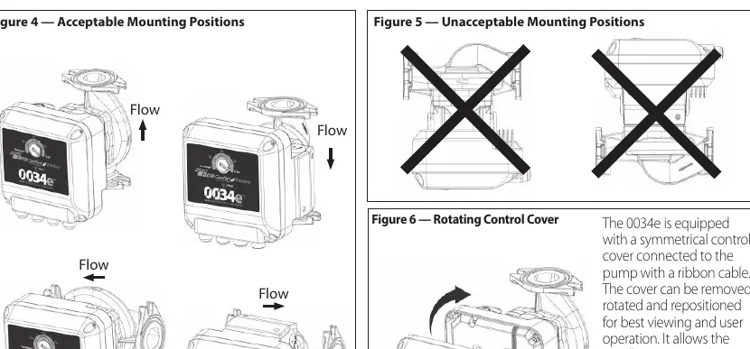
The circulator can be installed on either the supply or return side of the boiler. For optimal performance, it should pump away from the expansion tank. The motor must be mounted in a horizontal position. Use only the provided O-ring gaskets; do not use flat rubber gaskets. If installing at elevations over 5000 feet, a minimum fill pressure of 20 psi is required to prevent cavitation.
Wiring
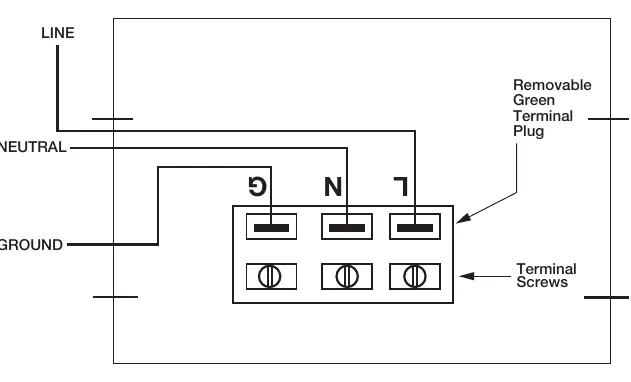
Disconnect AC power before wiring. The unit features dual electrical knockouts and a removable terminal strip. Connect Line/Hot to the L terminal, Neutral to the N terminal, and Ground to the G terminal. Use flexible conduit only. For 0-10V DC or PWM external control, follow the specific wiring procedure on page 9 of the manual.
Operating Modes
The circulator features 5 dial settings, adjustable with a flat screwdriver:
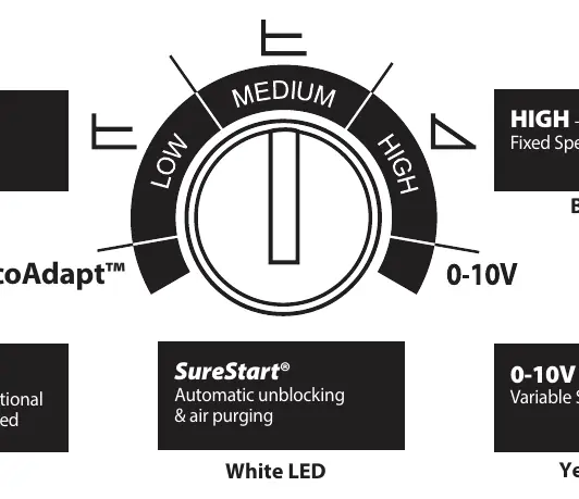
- TacoAdapt: Automatic, self-adjusting, proportional pressure (Violet LED).
- LOW: 13 ft. head constant pressure (Orange LED).
- MEDIUM: 26 ft. head constant pressure (Orange LED).
- HIGH: 34 ft. head max, fixed speed (Blue LED).
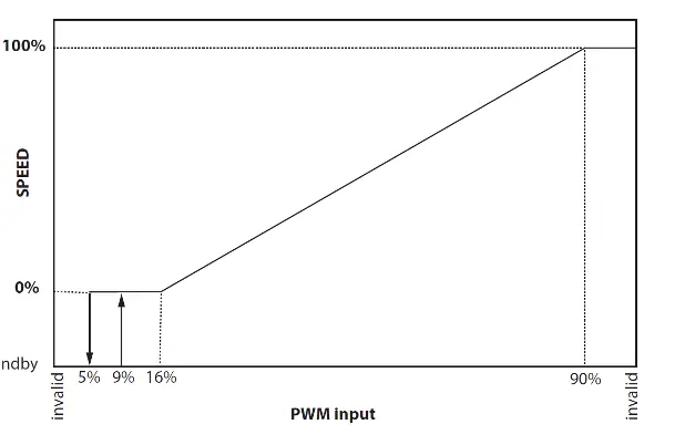
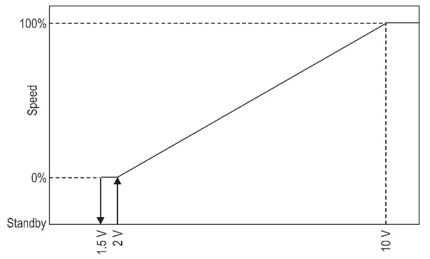
- 0-10V DC: Analog external input or PWM pulse width modulation (Yellow LED).
Troubleshooting
If the circulator is noisy, check for insufficient suction pressure or foreign bodies in the impeller. If the unit is not running despite power, verify the power supply, check for tripped circuit breakers, or ensure the unit is not overheating. A red LED indicates a blocked rotor; follow the unlocking procedure by disconnecting power, removing the motor from the casing, and cleaning the impeller.
Practical help
Common problems
Increase system suction pressure or disassemble the motor to clean the impeller of foreign bodies.
The system may be air-bound. Vent the system and repeat fill and purge steps.
Verify power supply voltage, check for tripped circuit breakers, or check motor connections.
Disconnect power, remove motor from casing, and clean the impeller. Follow the manual unlocking procedure.
Before use
- Ensure the system is filled with water or max 50% water/glycol solution.
- Verify the motor is mounted in a horizontal position.
- Check that the system is flushed of foreign matter.
- Ensure the power supply matches the nameplate data.
- Use only the provided O-ring gaskets for installation.
Specs in practice
- Maximum operating pressure
- 150 psi (10.3 bar).
- Fluid temperature range
- 14°F to 230°F (-10°C to 110°C).
- Electrical requirements
- 115/208/230V, 50/60 Hz, single phase.
Images and diagrams
- Figure 2 & 3: Piping diagrams showing preferred locations for circulators and zone valves.
- Figure 4 & 5: Acceptable and unacceptable motor mounting orientations.
- Figure 7: Dial settings and corresponding LED colors for operating modes.
- Figure 8: Step-by-step guide for external 0-10V DC/PWM signal wiring.
Model compatibility
- SS Model is suitable for open loop potable water systems.
- Not for use in swimming pool or spa areas.
- Use flexible conduit only; not for use with rigid conduit.
- Installations over 5000 feet require a minimum 20 psi fill pressure.

Manual page author
Emily Carter
User documentation editor
Prepares concise manual descriptions and highlights the most useful setup, operation, and maintenance information for readers.