Vermeiren EAGLE 620 150KG Patient Lift Parts List and Assembly Drawing
Official parts list and assembly drawing for the Vermeiren EAGLE 620 150KG patient lift. Includes exploded view, torque specifications, and maintenance requirements.
Table of contents
Important Assembly and Maintenance Information
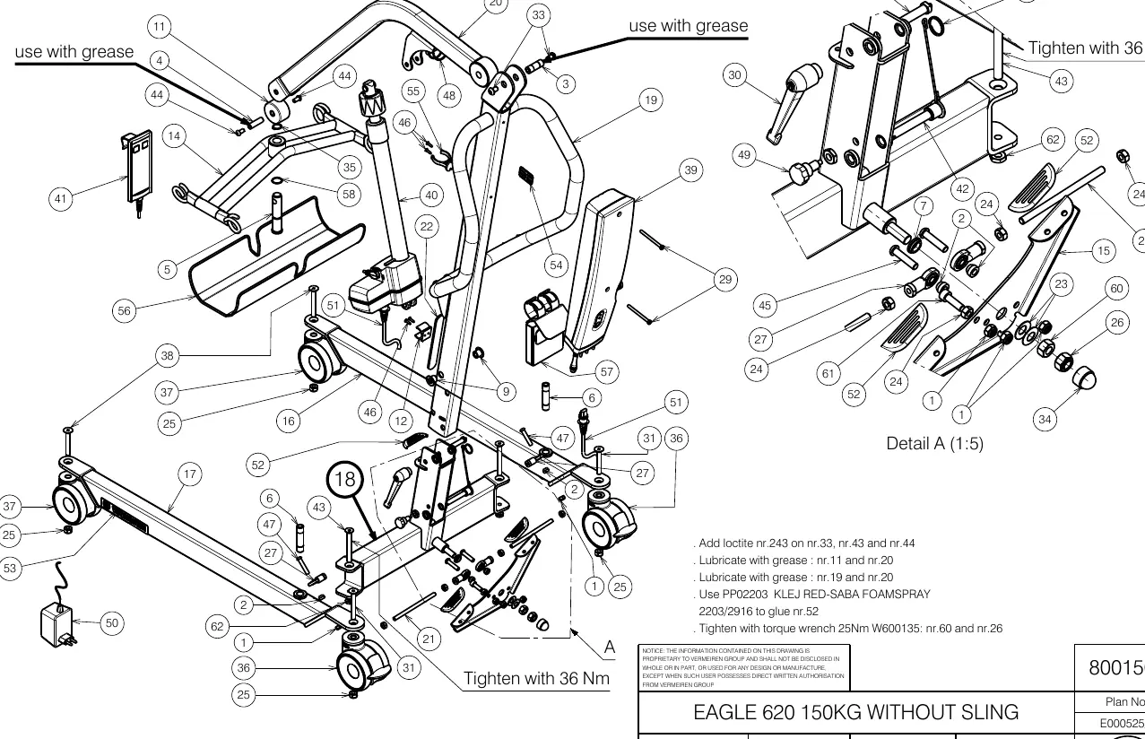
This document provides the official exploded view and parts list for the Vermeiren EAGLE 620 150KG patient lift. It is intended for use during assembly, maintenance, and repair. Ensure all assembly steps are followed precisely to maintain the safety and structural integrity of the device.
Assembly and Maintenance Requirements
When assembling or servicing the lift, adhere to the following technical specifications:
- Threadlocking: Apply Loctite 243 to parts 33, 43, and 44.
- Lubrication: Apply grease to parts 11, 20, 19, and 20.
- Adhesive: Use PP02203 KLEJ RED-SABA FOAMSPRAY (2203/2916) to glue part 52.
- Torque Settings: Tighten parts 60 and 26 using a torque wrench set to 25 Nm (W600135).
- General Tightening: Specific structural bolts indicated in the diagram must be tightened to 36 Nm.
Parts Identification
The document includes a comprehensive parts list table on page 2. Each component is identified by a reference number, plan code, article number, and the required quantity for assembly. Use these identifiers when ordering replacement parts or verifying the contents of the assembly kit.
Practical help
Common problems
Verify that all bolts are tightened to the specified torque (25 Nm or 36 Nm) as indicated in the assembly diagram.
Ensure that parts 11, 20, 19, and 20 have been properly lubricated with grease.
Before use
- Verify all bolts are tightened to the specified torque (25 Nm or 36 Nm).
- Ensure all moving parts are lubricated as specified.
- Check that Loctite 243 is applied to designated bolts (33, 43, 44).
- Confirm all parts listed in the table are present and correctly installed.
- Ensure part 52 is securely glued using the specified adhesive.

Manual page author
Michael Turner
Technical manual editor
Reviews PDF manuals for structure, safety notes, and practical product details so readers can find the right information quickly.