Wiring and Logic Diagram for Vollrath 2-Well Hot & Cold Drop-In
Technical wiring and ladder logic diagrams for the Vollrath 2-Well Hot & Cold Drop-In unit. This guide provides essential electrical schematics for models FC-6HC-02120 and FC-6HC-02120-AD.
Quick answers from the manual
Quick answer
- This document provides the 120V wiring and ladder logic diagrams for the Vollrath 2-Well Hot & Cold Drop-In unit, specifically for models FC-6HC-02120 and FC-6HC-02120-AD. p. 1, 2
Key actions
- Verify wiring connections using the provided diagram. p. 1
Technical specifications
| Parameter | Value | Meaning | Pages |
|---|---|---|---|
| Voltage | 120V | Operating voltage | p. 1, 2 |
Where to find it in the PDF
- Wiring Diagram p. 1
- Ladder Logic Diagram p. 2
Table of contents
Manual images
Click an image to enlargeQuick Guide from the Manual
This document contains the official wiring and ladder logic diagrams for the Vollrath 2-Well Hot & Cold Drop-In unit. It is intended for use by qualified service technicians to assist with installation, troubleshooting, and electrical maintenance. Always observe the viewer orientation notes provided in the diagrams to ensure correct interpretation.
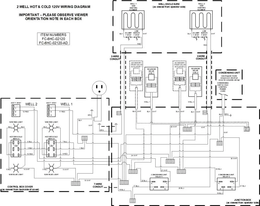
Wiring Diagram
The wiring diagram illustrates the physical electrical connections for the 120V system. It details the connections for the heating elements, solenoids, control box, and junction box. Technicians should use this diagram to verify wiring integrity and component connections.
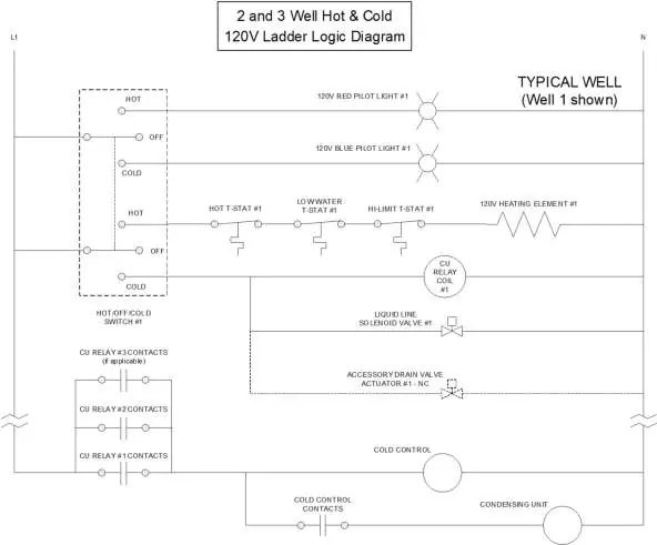
Ladder Logic Diagram
The ladder logic diagram provides a schematic representation of the electrical control sequence for a typical well. It outlines the operation of the hot/off/cold switch, thermostats, relays, and solenoid valves, helping to understand the control logic of the unit.
Practical help
Common problems
Verify electrical connections against the wiring diagram and check the status of the relays and thermostats.
Ensure you are observing the viewer orientation notes provided in each box of the wiring diagram.
Before use
- Verify the power supply is 120V.
- Ensure all electrical connections match the provided wiring diagram.
- Check the control box cover and junction box for proper wiring orientation.
- Verify the status of the heating elements and solenoid valves.

Manual page author
David Miller
Documentation analyst
Organizes user manual content into clear summaries, with attention to model details, product context, and everyday usability.