Quick Start Guide for Watteco Press’O 0-5V Atex Zone 1 Sensor
Quick start guide for the Watteco Press’O 0-5V Atex Zone 1 sensor, covering installation, LoRaWAN network provisioning, connector wiring, and safety requirements for explosive atmospheres.
Table of contents
Quick guide from the manual
This document provides essential instructions for the installation, operation, and maintenance of the Watteco Press’O 0-5V Atex Zone 1 sensor. Due to its certification for use in explosive atmospheres, all procedures must be performed by qualified personnel in accordance with EN 60079-14 standards.
Safety and usage recommendations
- Installation, maintenance, and use must be performed exclusively by personnel competent in electrical equipment for explosive atmospheres.
- Any repair or modification is strictly prohibited without written authorization from Watteco.
- To prevent electrostatic discharge, clean the product only with a damp cloth.
- Use only SAFT LS17500 batteries.
- Do not change the battery in an explosive atmosphere.
Start
To provision the device on your LoRaWAN network, use the keys provided on the secure platform. The device is controlled via an internal magnetic switch (ILS).
- ON: Hold the magnet for >1 second. The red LED will light up, followed by the green LED indicating network searching, and finally association.
- OFF: Hold the magnet for >5 seconds. The red LED will indicate the switching off process.
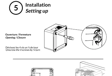
Installation
The device housing can be wall-mounted. To open or close the housing, unscrew the 4 screws by a 1/4 turn. Ensure the sensor is placed in a location with minimal obstacles to avoid excessive radio attenuation. You may verify radio coverage using a tool such as the Netw’O.
Connectors
The subbase connectivity is defined by a 6-point connector (red circle). The pinout is as follows:
- P1: OUT - V+ (~5.5Vdc@5mA)
- P2: GND
- P3: IN-Measure 1
- P4: GND
- P6: IN-Measure 2
- P7: GND
Technical specifications
- Reference: 50-70-114 (IP68) or 50-70-151 (IP55)
- Class: A
- Power Level: +14 dBm
- Measures: 0-5V
- Antenna: Internal
- Casing materials: ASA / PC
- Operating Temperature: -20°C to +50°C
Support and certifications
For further assistance, visit the support site at https://support.watteco.com/. Full declarations of conformity are available at https://www.watteco.com/assistance/download-center/.
Official resources from the manual
Practical help
Common problems
Ensure the number of obstacles between the sensor and the gateway is limited to maintain proper radio propagation.
Clean the product only with a damp cloth to prevent potential electrostatic charging hazards.
Before use
- Verify that the personnel performing installation are competent in explosive atmosphere equipment.
- Ensure you have the correct LoRaWAN network keys from the secure platform.
- Confirm you are using only SAFT LS17500 batteries.
- Check the IP rating (IP55 or IP68) based on your specific model reference (50-70-151 or 50-70-114).
Images and diagrams
- The device uses a magnetic switch (ILS) for ON/OFF operations.
- The connector pinout (P1-P7) is clearly defined for 0-5V measurement applications.
- Wall mounting requires unscrewing the 4 housing screws by a 1/4 turn.
Model compatibility
- Certified according to EN60079-0 ed. 6 and EN60079-11 ed.6.
- Ex ib IIB, IIC T4 Gb / Ex ib IIIC T135°C Db classification.
- Compatible with LoRaWAN networks.

Manual page author
Michael Turner
Technical manual editor
Reviews PDF manuals for structure, safety notes, and practical product details so readers can find the right information quickly.