Home / Security
Instruction Manual for Autonics BUP Series Photoelectric Sensors
Quick guide for Autonics BUP Series U-shaped photoelectric sensors. Includes wiring diagrams, operation mode selection, sensitivity adjustment, and technical specifications.
Table of contents
Manual images
Click an image to enlargeQuick Guide for BUP Series Sensors
The Autonics BUP Series are 1-channel U-shaped photoelectric sensors designed for industrial use. This manual covers installation, wiring, sensitivity adjustment, and technical specifications. Always ensure the power is disconnected before performing any wiring or inspection.
Installation and Mounting
When installing the sensor, consider the following:
- Environment: Avoid areas with flammable/explosive gas, high humidity, direct sunlight, radiant heat, vibration, or impact.
- Mounting: Use M5 screws (1.96 N·m torque) for 30mm sensing distance models or M8 screws (4.9 N·m torque) for 50mm models.
- Cable Handling: Do not bend the cable excessively or impact the unit with hard objects, as this may compromise water resistance.
- Testing: Always test the indicator functionality for the target object before final operation.
Wiring and Operation Modes
The sensors support NPN or PNP open collector outputs. Ensure the control wire is connected correctly to select the desired operation mode.
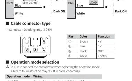
- Light ON Mode: Connect the control wire (white) to +V (brown).
- Dark ON Mode: Connect the control wire (white) to 0V (blue).
- Inductive Loads: When connecting inductive loads like relays or solenoid valves, use diodes or varistors to remove surge.
- Power Supply: Use a 12-24 VDC insulated/Class 2 power supply.
Sensitivity Adjustment
For models with sensitivity adjustment (BUP-□S-□), follow these steps using the provided screwdriver:
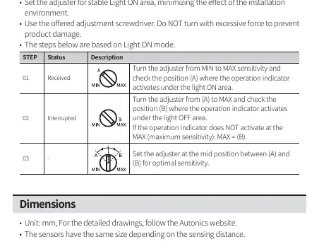
- Step 1: Turn the adjuster from MIN to MAX and identify position (A) where the operation indicator activates under the Light ON area.
- Step 2: Turn the adjuster from (A) to MAX and identify position (B) where the indicator activates under the Light OFF area.
- Step 3: Set the adjuster to the midpoint between (A) and (B) for optimal sensitivity.
Technical Specifications
Key parameters for the BUP Series:
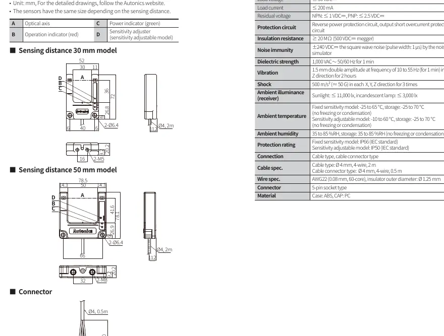
- Sensing Distance: 30mm or 50mm models available.
- Response Time: ≤ 1 ms.
- Protection Rating: IP66 for fixed sensitivity models; IP50 for sensitivity adjustable models.
- Power Supply: 12-24 VDC ±10%.
- Ambient Temperature: -25 to 65°C (fixed) or -10 to 60°C (adjustable).
Practical help
Common problems
Indicator does not activate at MAX sensitivity
Check the target position and environment; ensure the target is an opaque material.
Noise interference in output
Ground the F.G. terminal of noise-generating equipment (e.g., inverter, servo motor) and the sensor power supply.
Product water resistance compromised
Ensure the cable is not bent excessively and the unit has not been impacted by hard objects.
Before use
- Verify power supply is 12-24 VDC (insulated/Class 2).
- Check wiring connections against the diagram before applying power.
- Ensure the environment is free from flammable/explosive gas.
- Confirm the sensing target is an opaque material.
- Check the indicator works appropriately for the target position.
Specs in practice
- Sensing distance
- The range at which the sensor detects the target (30mm or 50mm).
- Response time
- The time taken for the sensor to react to a target (≤ 1 ms).
- Protection rating
- IP66 (dust-tight, water-resistant) for fixed models; IP50 (dust-protected) for adjustable models.
Images and diagrams
- Wiring diagram shows NPN and PNP output configurations with load connections.
- Operation timing chart illustrates the relationship between received light, indicator status, and transistor output.
- Connector pinout defines the function of each of the 4 pins.
Model compatibility
- Fixed sensitivity models are IP66 rated.
- Sensitivity adjustable models are IP50 rated.
- Ensure the control wire is connected to select Light ON or Dark ON mode.

Manual page author
David Miller
Documentation analyst
Organizes user manual content into clear summaries, with attention to model details, product context, and everyday usability.