HVAC / Ignition Systems
Beckett GeniSys 7565 and 7585 120V Advanced Burner Control
Quick guide for the Beckett GeniSys 7565 and 7585 120V Advanced Burner Controls. Includes installation, wiring, operation, and troubleshooting steps.
Table of contents
Manual images
Click an image to enlargeQuick guide from the manual
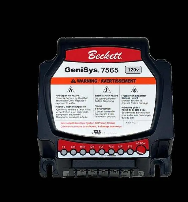
This manual provides installation and operation instructions for the Beckett GeniSys 7565 and 7585 120V Advanced Burner Controls. These units are designed for residential and light commercial oil burners used in boilers, furnaces, and water heaters with firing rates less than 20 GPH. Key features include diagnostics via the myTechnician app, 8 status lights, and a water-resistant case.
Product Description
The GeniSys control is a primary safety control for oil burners. It is compatible with #2 Fuel oil, up to 100% biodiesel, and up to 100% renewable diesel. It supports interrupted or intermittent duty ignition and is compatible with both mechanical and power-stealing thermostats.
Installation and Wiring
Caution: Incorrect wiring will result in improper control operation. The control wiring label colors may not match the wire colors of the burner or other manufacturers' controls. Always wire according to the appliance manufacturer's specifications.

The control features top/front face connections for low voltage (24 Vac) inputs, including thermostat red (TR), thermostat white (TW), thermostat common (TC), and air switch inputs. Under-side connections are used for high voltage power and motor connections.
Operation
The control features an ACTION button used for various operations:
- Resetting Lockouts: A 1-second tap exits a soft lockout; holding for 15+ seconds exits a hard lockout.
- Pump Priming: To enter Pump Prime mode, hold the ACTION button for 15+ seconds to enable, then perform a 1-second tap on the next call-for-heat. This energizes the igniter, motor, and oil solenoid valve for 4 minutes, allowing the technician to prime the pump without jumpering the cad cell.
- Pausing Burner Operation: Hold the button for 1+ seconds.
Safety Features
The control includes a Safe Start Check feature. To perform this check: place a jumper across the cad cell terminals, initiate a call for heat, and verify that the burner does not start. The SYS light should be green, the FLM light should be yellow, and the control should remain in Standby mode. Remove the jumper after the test.
Electrical Ratings
Power: 120 Vac nominal (102 to 132 Vac), 60 Hz.
Inputs: Thermostat voltage is 24 Vac nominal. Combustion air/blocked vent inputs require 10mA @ 24Vac (front) or 1.9mA @ 120Vac (underside).
Outputs: Motor output is 120 Vac, 10 max FLA, 60 max LRA. Igniter output is 120 Vac, 3 A max.
Practical help
Common problems
Burner does not start during safe start check
Verify SYS light is green, FLM light is yellow, and control is in Standby mode.
Pump not primed
Use Pump Prime mode: hold ACTION button for 15+ seconds to enable, then perform a 1-second tap on the next call-for-heat.
Incorrect control operation
Ensure wiring matches the appliance, not just the control label colors.
Before use
- Verify 120 Vac power supply
- Ensure burner is compatible with #2 Fuel oil, biodiesel, or renewable diesel
- Check thermostat connections (TR, TW, TC)
- Verify air switch installation (if applicable)
Specs in practice
- Motor Output
- 120 Vac, 10 max FLA, 60 max LRA
- Igniter Output
- 120 Vac, 3 A max
Images and diagrams
- Top and Front Face Connections: Shows thermostat and air switch inputs.
- Under Side Connections: Shows power and motor connections.
- ACTION Button: Used for resetting lockouts and entering pump prime mode.
Model compatibility
- Compatible with residential and light commercial oil burners (boiler, furnace, water heater) with firing rates less than 20 GPH.
- Compatible with mechanical and power stealing thermostats.

Manual page author
Emily Carter
User documentation editor
Prepares concise manual descriptions and highlights the most useful setup, operation, and maintenance information for readers.