HVAC / Burner Controllers
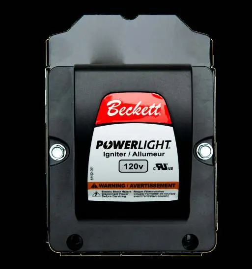
Beckett PowerLight 120VAC Igniter Installation Instructions
Quick guide for the Beckett PowerLight 120VAC Igniter. Includes installation steps, wiring requirements, technical specifications, and safety warnings for burner systems.
Table of contents
Quick guide from the manual
This document provides installation instructions for the Beckett PowerLight 120VAC Igniter. This device is designed for use with 120VAC burner systems and is rated for continuous duty. Installation and service must be performed by a qualified service technician.
Safety Warnings
Electrical Shock Hazard: Failure to disconnect all power sources could result in severe personal injury or death. Always disconnect all electrical power to the burner before servicing. Note that more than one disconnect switch may be in the supply circuit. Ensure the burner housing and circuit are connected to earth ground.
Specifications
- Input Voltage: 102-132 VAC, 50/60 Hz
- Output Voltage: 20 kV
- Output Current: 25 mA RMS
- Input Current: 0.2A RMS
- Ambient Operating Temperature: -40 to +150° F
- Storage Temperature: -40 to +150° F
- Moisture: 5% to 95% Relative Humidity, Condensing
Installation Steps
- Locate the igniter blue "hot" and white "neutral" input leads.
- Install the 32302 igniter gasket, if required, and route the leads through the appropriate base plate lead exit hole. Ensure leads are not being crushed.
- Mount the igniter flush to the base plate with the supplied mounting screws.
- Use #6 x 7/16" screws for bottom mounting holes. Use #10 thread-forming paint-scraping screws for the two top mounting holes (for 51771U and 51824U models).
- Tighten all screws securely.
- Install the barrier and base plate gaskets for AF, AFG models. Use gaskets for other burner models as required by the manufacturer.
- Mount the assembled unit to the burner using the supplied screws.
- Use "paint scraping" screws for all burners (2 at the hinge and 2 for non-hinged base plates) to provide effective grounding.
- Verify the burner is properly grounded.
- Route the igniter input leads carefully to prevent pinching during closing. Install the cad cell if applicable.
- Fasten cad cell leads to the control. Wire white to neutral and blue to the primary control ignition lead. Refer to the control or appliance manufacturer’s wiring diagram.
- Verify the igniter secondary output terminals are correctly arranged to make good electrical contact with the oil burner electrodes.
- Close the igniter and install/tighten the front base plate retaining screws (2 or 4 screws depending on hinge).
- Reconnect electric power to the burner circuit.
- Verify with instruments that the burner is adjusted to the manufacturer’s recommended settings.
- Cycle the burner several times to verify prompt and smooth ignition.
Compatibility
The igniter is compatible with various base plates, including models 51771U, 51824U, 51825U, 51827U, 51826U, and 51840U. It fits Beckett residential and commercial burners as well as many other vendors' base plates. For non-Beckett base plates, verify that the igniter fit is free of air leakage.
Practical help
Common problems
Igniter failure
Do not use this igniter beyond its design specifications.
Air leakage between base plate and igniter
Verify the igniter fit is free of air leakage when using non-Beckett base plates.
Improper ignition
Cycle the burner several times to verify prompt and smooth ignition before leaving.
Before use
- Ensure all power sources are disconnected before servicing.
- Verify the burner is properly grounded.
- Check that leads are not being crushed during installation.
- Ensure the igniter is mounted flush to the base plate.
- Verify secondary output terminals make good electrical contact with oil burner electrodes.
Specs in practice
- Input Voltage
- 102-132 VAC, 50/60 Hz
- Output Voltage
- 20 kV
- Output Current
- 25 mA RMS
- Ambient Operating Temperature
- -40 to +150° F
Images and diagrams
- Figure 1 illustrates the igniter assembly components, showing the placement of the igniter, baseplate, mounting screws, and gaskets.
Model compatibility
- Compatible with Beckett residential and commercial burners.
- Fits various base plates including 51771U, 51824U, 51825U, 51827U, 51826U, and 51840U.
- Can be adapted to many other vendors' base plates.

Manual page author
Emily Carter
User documentation editor
Prepares concise manual descriptions and highlights the most useful setup, operation, and maintenance information for readers.