Parts List for Bosch GWS 13-125CIE Angle Grinder
Access the official parts list and exploded view diagram for the Bosch GWS 13-125CIE angle grinder. Includes component identification and essential torque specifications for maintenance and repair.
Table of contents
Quick Guide from the Manual
This document serves as the official parts list and exploded view diagram for the Bosch GWS 13-125CIE angle grinder. It is designed to assist in identifying components for maintenance and repair purposes.
Exploded View and Component Identification
The provided diagram illustrates the assembly of the angle grinder, including the motor, gear housing, handle, and internal electrical components. Each part is marked with a reference number to facilitate the identification of replacement parts.
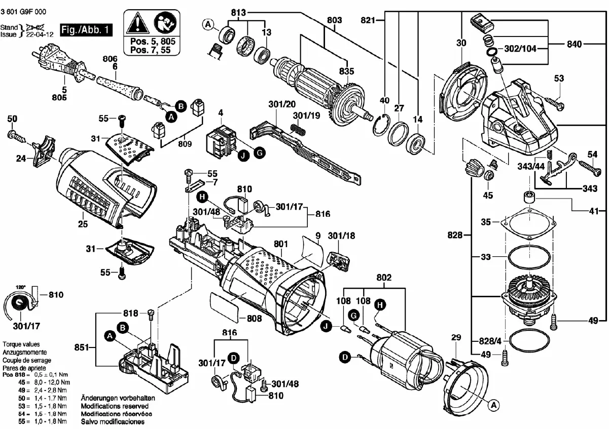
Torque Specifications
When reassembling the tool, it is critical to adhere to the specified torque values to ensure safety and proper operation. The following torque settings are required for specific components:
- Pos 818: 0.5 ± 0.1 Nm
- Pos 45: 8.0 - 12.0 Nm
- Pos 49: 2.4 - 2.8 Nm
- Pos 50: 1.4 - 1.7 Nm
- Pos 53: 1.5 - 1.8 Nm
- Pos 54: 1.5 - 1.8 Nm
- Pos 55: 1.0 - 1.8 Nm
Manufacturer information
Bosch
Practical help
Before use
- Verify the model number matches GWS 13-125CIE before ordering parts.
- Ensure the tool is disconnected from the power source before disassembly.
- Use appropriate torque tools to match the specified Nm values during reassembly.
Specs in practice
- Torque (Pos 818)
- 0.5 ± 0.1 Nm
- Torque (Pos 45)
- 8.0 - 12.0 Nm
- Torque (Pos 49)
- 2.4 - 2.8 Nm
- Torque (Pos 50)
- 1.4 - 1.7 Nm
- Torque (Pos 53)
- 1.5 - 1.8 Nm
- Torque (Pos 54)
- 1.5 - 1.8 Nm

Manual page author
Emily Carter
User documentation editor
Prepares concise manual descriptions and highlights the most useful setup, operation, and maintenance information for readers.