HVAC / Air Handlers
Installation and Operating Instructions for Bosch IDS Heat Pump 115V Modular Blower
Quick guide for the Bosch IDS Heat Pump 115V Modular Blower. Includes installation, wiring diagrams, airflow settings, maintenance, and troubleshooting codes.
Table of contents
Manual images
Click an image to enlargeQuick Guide from the Manual
This document provides installation and operating instructions for the Bosch IDS Heat Pump 115V Modular Blower. It is intended for qualified contractors and authorized installers. Key safety warnings include handling A2L refrigerants, ensuring proper electrical grounding, and avoiding installation in areas with flammable materials or high humidity. The unit supports upflow, downflow, and horizontal applications.
Installation and Applications
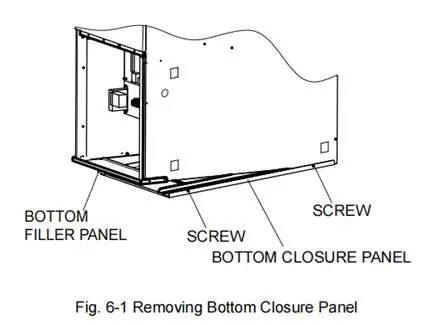
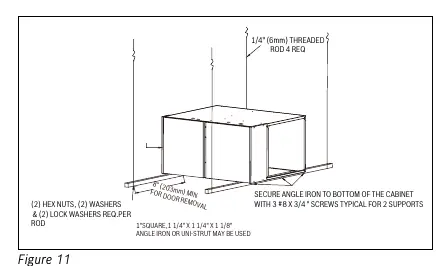
The unit can be installed in various configurations. For vertical upflow with bottom return, the bottom closure panel must be removed. For horizontal installations in attics or crawl spaces, the unit must be suspended or supported on a non-combustible platform, with adequate clearance for service and drain traps. A drain pan is mandatory if the unit is installed above a conditioned area.
Electrical Wiring
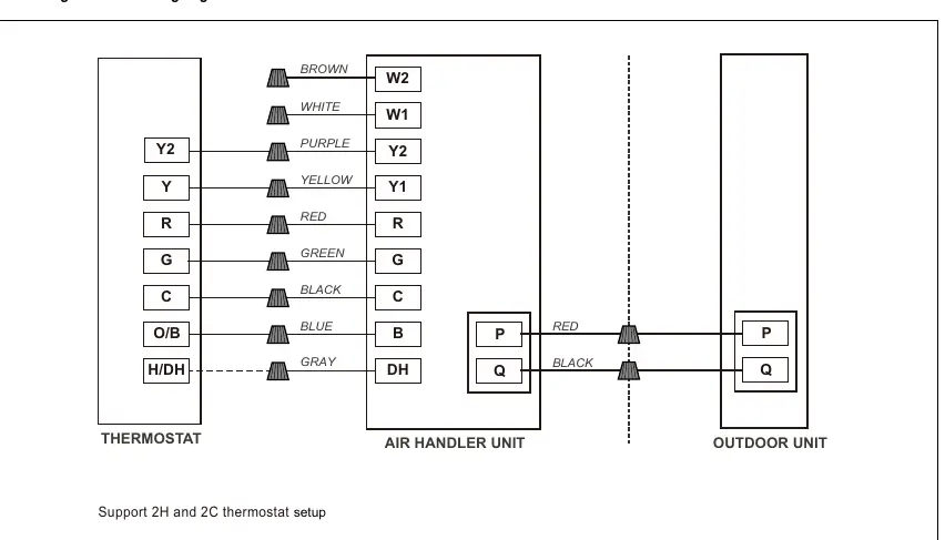
The system supports two wiring modes: PQ communication (for compatible Bosch ODU) and conventional 24VAC non-communicating thermostat control. Wiring must comply with the National Electric Code. Low voltage control wiring should be separated from high voltage power wiring. Dip switches on the control board must be configured correctly for the chosen communication mode.
Airflow Performance
The blower features 5 tap speeds. Installers must refer to the Airflow Performance Table (Table 6) to select the appropriate speed tap based on the evaporator coil's requirements and external static pressure. Proper duct design is critical to system performance.
Air Filter
Filters are not factory-installed and must be field-supplied. High-efficiency filters or electronic air filtration systems should be installed carefully to avoid reducing airflow. Filters with MERV ratings between 8-11 are recommended.
Maintenance and Troubleshooting
Regular annual maintenance by a qualified technician is required, including inspection of the air filter, blower wheel, motor, coils, and drain lines. The unit features an LED indicator for fault diagnostics. Flashing codes correspond to specific issues such as refrigerant leaks, sensor faults, or communication errors.
Manufacturer information
Bosch
Practical help
Common problems
Continuous flashing LED
Indicates R454B refrigerant leakage. Check line set for leaks, ventilate the area, and replace the sensor.
3 flashes (LED)
Indoor unit A2L refrigerant sensor fault. Check if ambient temperature exceeds 140°F; if not, replace the sensor.
5 flashes (LED)
Communication fault between IDU and ODU. Check PQ wire connections, dip switch settings, or replace control board.
8 flashes (LED)
A2L refrigerant sensor past service life. Replace the sensor.
9 flashes (LED)
Dip switch SW7-2 does not match refrigerant sensor. Verify dip switch settings and sensor type.
Before use
- Ensure the unit is permanently grounded.
- Verify power supply matches the unit nameplate (115/120V).
- Confirm filters are installed (field supplied).
- Check that airflow is not obstructed.
- Verify dip switch settings for communicating or non-communicating mode.
- Ensure drain pan is installed if the unit is above a conditioned area.
Specs in practice
- Blower Power
- 3/4 hp or 1 hp depending on the specific model.
Images and diagrams
- Figure 7: Instructions for removing the bottom closure panel for upflow applications.
- Figure 11-12: Methods for suspending the cabinet in horizontal installations.
- Figure 18-19: Wiring diagrams for communicating thermostat setups.
- Figure 23-24: Wiring diagrams for non-communicating thermostat setups.
- Figure 25: Comprehensive wiring diagram and dip switch settings.
Model compatibility
- Compatible with Bosch R454B products.
- Communicating mode requires IDS Premium (BOVA20) or IDS Light (BOVA15) outdoor unit.
- Not approved for installation in mobile homes, recreational vehicles, or outdoors.

Manual page author
David Miller
Documentation analyst
Organizes user manual content into clear summaries, with attention to model details, product context, and everyday usability.