HVAC / Thermostats & Controls
Operation and maintenance instructions for Systemair VR 300 ECV/B Air Handling Unit
Quick guide for the Systemair VR 300 ECV/B air handling unit. Includes maintenance schedules, filter replacement, troubleshooting, and operation settings.
Table of contents
Manual images
Click an image to enlargeQuick guide from the manual
The Systemair VR 300 ECV/B is an air handling unit designed for continuous operation. Maintenance should be performed 3-4 times per year to ensure efficiency. Always disconnect the mains supply before performing any electrical work or maintenance. Use protective gloves when handling the unit due to sharp edges.
Operation
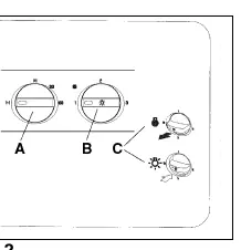
The airflow can be controlled via an external 3-step speed regulator or a connected cooker hood.
- Min (1): Minimum ventilation, used during holidays or when the building is not in use.
- Norm (2): Normal ventilation adapted to the building.
- Max (3): Forced ventilation, used when extra airflow is required.
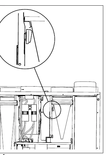
Supply air temperature: The temperature can be adjusted using a switch located inside the unit. Turning the switch clockwise increases the temperature, while counter-clockwise decreases it. The unit features an automatic electrical heater battery that switches on if heat recovery is insufficient.
Summer operation: If the supply air temperature exceeds the set value, the rotor stops to prevent heat recovery.
Extract from cooker
The unit can be connected to a specific cooker hood. The hood must have a damper that leaves no opening when closed. When forced ventilation is activated via switch A, the fans automatically switch to Max speed (3). The extract air from the cooker bypasses the heat exchanger.
Maintenance
Maintenance should be performed 3-4 times per year.
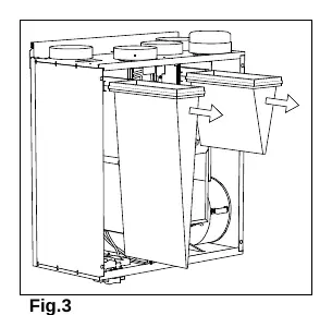
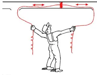
- Filter change: Replace fresh air/extract filters 1-2 times per year. Pull the filter frame straight out to remove.
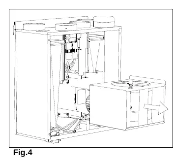
- Heat exchanger/Rotor belt: Check the belt during filter changes. Ensure it is undamaged and tight enough to move the heat exchanger wheel. Clean the exchanger block every 3 years in hot soapy water (do not use ammonia-based detergents).
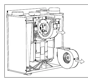
- Fans: Clean every 3 years. Remove fans by unplugging electrical couplings and clean with a soft brush or cloth. Do not use water.
- Extract louvers and inlet diffusers: Wash in hot soapy water as required. Do not exchange positions.
- Fresh air intake: Check at least twice a year for leaves or pollution.
- Duct system: Clean every 5 years using a brush soaked in hot soapy water.
Troubleshooting
Before calling for service, check the following:
- Fan(s) do not start: Check fuses and ensure all plugs are connected.
- Reduced airflow: Check control panel settings, filter status, diffuser/louver cleanliness, and ensure the air intake is not clogged.
- Cold supply air: Check the temperature setting and ensure the fire thermostat has not tripped (reset by pressing the red button in the unit).
- Noise/vibrations: Clean fan impellers and ensure fan screws are tightened.
Service
If service is required, locate the type label on top of the unit. Note the item number and production number before contacting your service representative.
Practical help
Common problems
Fan(s) do not start
Check that all fuses are intact and that all plugs (mains supply and fan plugs) are properly connected.
Reduced airflow
Check airflow settings, replace filters if necessary, clean diffusers/louvers, check if the air intake is clogged, and inspect ducts for damage or dust buildup.
Cold supply air
Check the supply air temperature setting on the control switch. Check if the fire thermostat has tripped and reset it by pressing the red button inside the unit.
Noise or vibrations
Clean the fan impellers and ensure the screws holding the fans are tightened.
Before use
- Ensure filters are correctly mounted in their place.
- Verify that the system is connected to the mains power supply.
- Check that the cooker hood damper is closed if not in use.
- Ensure the rotor motor is not exposed to moisture.
Images and diagrams
- Fig 1: Location of the supply air temperature switch inside the unit.
- Fig 2: Controls for the cooker hood damper and fan speed.
- Fig 3: How to remove the filter frame for replacement.
- Fig 4: Removing the heat exchanger block for cleaning.
- Fig 5: Removing the fans for cleaning.
Model compatibility
- The cooker hood must be equipped with a damper that leaves no opening in the closed position.
- Tumble dryers must not be connected directly to the ventilation system.
- Diffusers and louvers must not be exchanged between rooms.

Manual page author
Michael Turner
Technical manual editor
Reviews PDF manuals for structure, safety notes, and practical product details so readers can find the right information quickly.