HVAC / Air Conditioners
Installation Guide for Bryant 135SAN Air Conditioner
A comprehensive installation guide for the Bryant 135SAN air conditioner. This manual covers safety requirements, mounting, refrigerant piping, electrical connections, system startup, and charging procedures.
Table of contents
Manual images
Click an image to enlargeQuick guide from the manual
This installation guide is intended for EPA-qualified personnel only. The Bryant 135SAN air conditioner uses R-454B refrigerant. Before starting, ensure you have read the entire manual. Key safety requirements include using non-sparking tools for A2L refrigerants, having a refrigerant detector present, and ensuring all electrical disconnects are locked out during installation.
Installation and mounting
The unit must be installed on a solid, level mounting pad. For rooftop applications, mount on a level platform above a load-bearing wall to minimize vibration. Ensure the unit is at least 6 inches above the roof surface. Maintain the following clearance requirements for proper airflow and service:

- Service end: 24 inches
- Above unit: 48 inches
- One side: 6 inches
- Remaining sides: 12 inches
Piping connections
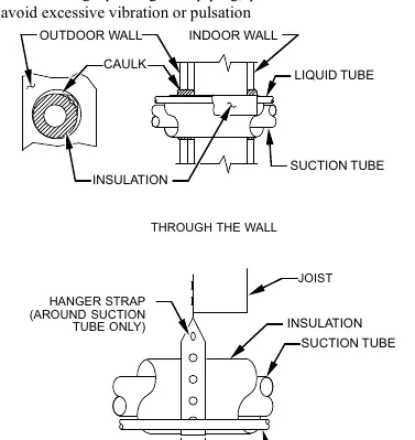
Refrigerant tubes must be protected from physical damage and vibration. When passing through walls, seal openings with RTV or pliable caulk. Use factory-supplied liquid-line filter driers. If brazing, wrap service valves with a wet cloth to prevent heat damage and remove valve cores before brazing. The system must be evacuated to 500 microns using a vacuum pump.
Electrical connections
Ensure field wiring complies with local and national codes. The unit requires an uninterrupted ground connection. Control wiring should be 18 AWG color-coded wire (use 16 AWG if the thermostat is over 100 ft away). All wiring must be separated from incoming power leads. For 3-phase units, a factory-installed monitor checks for phase problems; if the LED flashes, interchange two field-wiring leads on the contactor.
System start-up and charging
Follow these steps to start the system:
- After evacuation, fully open liquid and vapor service valves.
- Replace stem caps and tighten with a wrench (1/12 turn past finger-tight).
- Close electrical disconnects to energize the system.
- Set the thermostat to COOL and fan to ON or AUTO.
- Operate for 15 minutes before checking the refrigerant charge.
For units with a TXV, use the subcooling method to check or adjust the charge. Ensure outdoor temperatures are between 70°F and 100°F and indoor temperatures are between 70°F and 80°F for accurate readings.
Practical help
Common problems
3-Phase Monitor LED is flashing
Indicates reversed phase. Disconnect power and interchange 2 field-wiring leads on the unit contactor.
Noise in living area
Often caused by gas pulsations from improper installation. Ensure proper tubing isolation and avoid rigid wire/strap contact with tubing.
System not starting
Check thermostat wiring, ensure power is supplied, and verify 3-phase monitor status.
Before use
- Verify unit rating plate matches job specifications.
- Ensure mounting pad is solid and level.
- Check for refrigerant leaks using a detector.
- Confirm all electrical connections are secure.
- Ensure service valves are closed until ready for operation.
Specs in practice
- Operating Ambient
- Minimum 55°F (13°C) in cooling mode.
- Vacuum Level
- 500 microns required for proper system evacuation.
Images and diagrams
- Fig 1: Connecting Tubing Installation showing hanger straps and wall penetration.
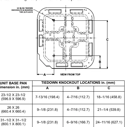
- Fig 2: Tiedown Knockout Locations for base pan.
- Fig 6: Line Connections for power and ground.
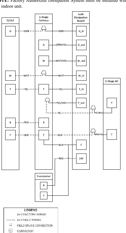
- Fig 7: Generic Wiring Diagram for thermostat connections.
- Fig 8: 3-Phase Monitor LED status indicators.
Model compatibility
- For use with R-454B indoor units only.
- 3-phase scroll compressors are rotation sensitive.
- Use copper wire only between disconnect switch and unit.

Manual page author
Michael Turner
Technical manual editor
Reviews PDF manuals for structure, safety notes, and practical product details so readers can find the right information quickly.