Tools / Power Tools
Centurion 0000.D.01.0012 Anti-Lift Brackets Installation Guide
Installation guide for Centurion 0000.D.01.0012 Anti-Lift Brackets. Learn how to properly mount these security brackets to sliding gate systems, including welding and fastening procedures for steel and wall installations.
Table of contents
Quick guide from the manual
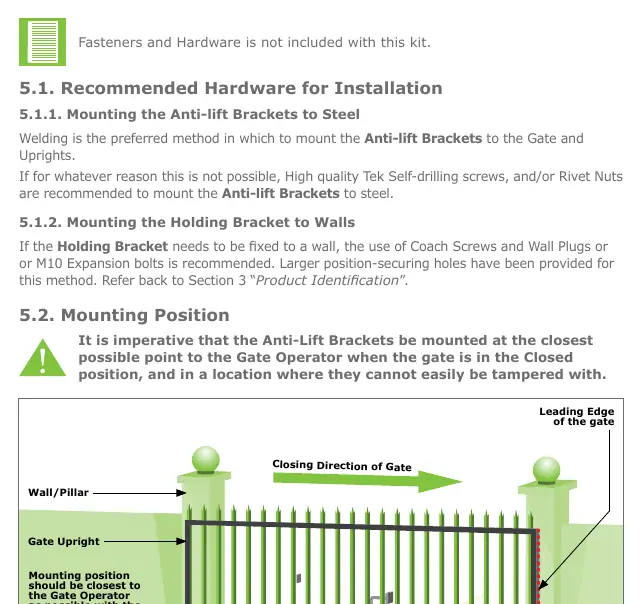
The Centurion Anti-Lift Brackets are designed to enhance the mechanical security of sliding gate systems by preventing the gate from being forcibly lifted off its track. These brackets act as a physical barrier and are essential for environments where perimeter integrity is a priority. The most critical aspect of installation is mounting the brackets at the closest possible point to the Gate Operator while the gate is in the fully closed position, ensuring they cannot be easily tampered with.
Product Identification
The kit consists of two main components:
- Locking Bracket: The component attached to the gate itself.
- Holding Bracket: The component attached to the wall or support post.
Both brackets feature various adjustment slots (7mm and 11mm) to allow for fine-tuning during installation.
Required Tools and Equipment
To install the brackets, you will need the following tools:
- Hammer and Spirit Level
- Electric Drill with 6mm steel/masonry bits and 10mm drill bit
- 13mm Sockets, Socket Wrench, and Extension
- Welding Machine (if welding) or Tek Self-drilling screws and socket
- Angle Grinder and Hacksaw
- Measuring Tape and Marking Pen/Chalk
- G-clamp(s)
- Safety Equipment (goggles, gloves, etc.)
Installation
Mounting Position: The brackets must be mounted as close as possible to the Gate Operator when the gate is in the closed position. If the gate operator uses Origin Magnets, mount the brackets higher on the support post (no more than 1 meter above the operator pinion) to avoid interference.
Mounting to Steel: Welding is the preferred method for mounting to steel gates and uprights. If welding is not possible, use high-quality Tek Self-drilling screws or Rivet Nuts.
Mounting to Walls: Use Coach Screws with Wall Plugs or M10 Expansion bolts. The Holding Bracket has specific 11mm masonry position-securing holes for this purpose.
Mounting Procedure:
- Test Fit: Position the brackets to find the optimal orientation for your site.
- Marking: Mark the position on the wall or support post.
- Fixing: Secure the Holding Bracket using your chosen method (weld or screws). Trim off any excess material if necessary for a neater finish.
- Fine-tuning: Use the vertical adjustment holes on the Holding Bracket or horizontal adjustment holes on the Locking Bracket to align the components.
- Locking Bracket: Attach the Locking Bracket to the gate upright. Ensure the Locking Pin lines up and slots into the Locking Slot of the Holding Bracket.
- Testing: Run a full open and close cycle to ensure smooth movement and no catch points.
Additional Recommendations
For sites without a catch post on the closing side, it is recommended to install a second set of Anti-lift Brackets on the leading edge of the gate. These should be installed at the same height as the first set. Additionally, installing a Centurion GLX900 Gate lock is recommended for further security.
Practical help
Common problems
Interference with Gate Operator origin magnets
Mount the Anti-lift Brackets higher on the wall or support post, but no more than 1 meter above the gate operator pinion.
Catch points during gate movement
Ensure the Locking Pin on the Locking Bracket is correctly aligned with the Locking Slot on the Holding Bracket and perform a full test cycle.
Installation not neat
Trim off any excess material from the Holding Bracket after securing it.
Before use
- Ensure the gate is in the fully closed position before marking positions.
- Verify that the chosen mounting location does not interfere with the gate operator.
- Test fit both brackets before final welding or screwing.
- Ensure all safety equipment (goggles, gloves) is worn during installation.
- Check that the Locking Pin aligns with the Locking Slot.
Specs in practice
- Locking Bracket Length
- 98.9mm total length.
- Holding Bracket Length
- 154mm total length.
- Adjustment Slots
- 7mm slots for fine-tuning position; 11mm holes for masonry fixings.
Images and diagrams
- Figure 6 and 7 show various orientation options for mounting on steel uprights and walls.
- Figure 9 and 10 illustrate the difference between welding and using Tek screws for the Holding Bracket.
- Figure 12 shows the correct alignment of the Locking Pin into the Locking Slot.
Model compatibility
- Compatible with standard sliding gate systems.
- Requires specific hardware (not included) depending on mounting surface (steel vs. wall).

Manual page author
Emily Carter
User documentation editor
Prepares concise manual descriptions and highlights the most useful setup, operation, and maintenance information for readers.