Electronics / Televisions
Chamberlain 050DCRJWFMC Logic Board Replacement Guide
A comprehensive guide for replacing the logic board on the Chamberlain 050DCRJWFMC garage door opener, including installation steps, travel programming, force setup, and safety testing procedures.
Table of contents
Manual images
Jump to the sectionQuick guide from the manual
This document provides instructions for replacing the logic board on the Chamberlain 050DCRJWFMC garage door opener. It covers the physical replacement, travel limit programming, automatic force setup, and mandatory safety system testing. Warning: Always disconnect all electric and battery power before performing any service. Wear protective gloves and eye protection when working near the battery compartment.
Logic Board Replacement
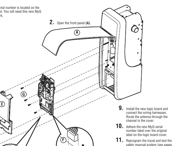
- Disconnect power and open the front panel (A).
- Remove the battery cover, disconnect the battery, and set it aside (B).
- Apply the Step Saver sticker under the yellow program button.
- Disconnect all wires from the safety reversing sensors, door control, door lock, and cable tension monitor (C).
- Remove the receiver logic board cover (D).
- Disconnect all wiring harnesses (E).
- Remove the four screws securing the logic board (F), remove the board, and discard it.
- Install the new logic board and reconnect all wiring harnesses. Route the antenna through the channel in the cover.
- Adhere the new MyQ serial number label over the original label on the cover.
- Reprogram travel limits and test the safety reversal system.
- Program all remote controls and keyless entries.
- Use the MyQ app to add the new serial number to your account.
Travel and Force Adjustment
After replacing the board, you must program the travel limits:
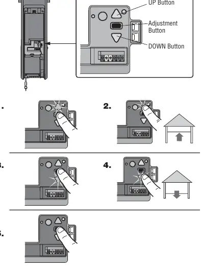
- Press and hold the Adjustment Button until the UP button flashes or a beep is heard.
- Press and hold the UP button until the door reaches the desired open position.
- Press and release the Adjustment Button; the lights will flash twice and the DOWN button will flash.
- Press and hold the DOWN button until the door reaches the desired closed position.
- Press and release the Adjustment Button; the lights will flash twice.
Once travel limits are set, the opener will automatically perform the Automatic Force Setup. The opener will move the door open and closed, beeping three times upon successful completion.
Safety Testing
Mandatory tests must be performed after any adjustment:
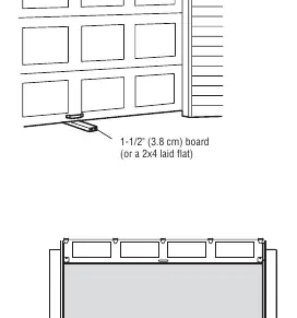
- Safety Reversal System: Place a 1-1/2 inch (3.8 cm) board on the floor under the door. The door must reverse upon contact.
- Protector System: Place an obstruction in the door's path; the door should not move more than 1 inch.
- Cable Tension Monitor: Ensure the monitor is flush with the wall and clicks when pushed.
- Automatic Garage Door Lock: Verify the lock bolt retracts before the door moves and engages when fully closed.
Manufacturer information
Chamberlain
Practical help
Common problems
Garage door opener lights flash 5 times during travel programming.
Programming has timed out. Restart the Program the Travel process from step 1.
Automatic Force Setup fails (one long beep).
The setup did not complete successfully. Restart the Program the Travel process from step 1.
Door stops but does not reverse during safety test.
Review installation steps, repeat the Program the Travel process, and re-test. If it continues to fail, contact a trained door systems technician.
Remote control does not work after board replacement.
Reprogram the remote control using the learn button on the garage door opener or via the door control menu.
Before use
- Disconnect all electric and battery power.
- Wear protective gloves and eye protection.
- Ensure you have the new MyQ serial number from the replacement label.
- Verify the cable tension monitor is mounted flush with the wall.
- Ensure the door is fully closed before manual operation or testing.
Specs in practice
- Safety Reversal Test Object
- A 1-1/2 inch (3.8 cm) board or a 2x4 laid flat must be used to test the safety reversal system.
- Diagnostic Code 3-5
- Indicates the cable tension monitor has been activated.
- Security+ 2.0
- The required remote control technology; older LiftMaster remotes are not compatible.
Images and diagrams
- Page 1 shows the step-by-step removal and installation of the logic board, including wiring harness locations.
- Page 2 illustrates the Adjustment Button, UP/DOWN buttons, and the travel programming sequence.
- Page 3 details the safety test setup with the 1-1/2 inch board and the emergency release handle operation.
Model compatibility
- Only Security+ 2.0 remote controls are compatible.
- Older LiftMaster remote controls are not compatible with this logic board.

Manual page author
David Miller
Documentation analyst
Organizes user manual content into clear summaries, with attention to model details, product context, and everyday usability.