Electronics / Televisions
Chamberlain 050DCRJWF Garage Door Opener Logic Board Replacement Guide
A comprehensive guide for replacing the logic board on your Chamberlain garage door opener, including step-by-step installation, door profile configuration, travel limit programming, and safety system testing.
Table of contents
Manual images
Jump to the sectionQuick guide from the manual
This document provides instructions for replacing the logic board (Model 041DJ003MC) on your Chamberlain garage door opener. The process involves physical installation, setting the door profile based on your drum size, programming travel limits, and performing mandatory safety tests. Always disconnect power before starting.
Installation
- Disconnect all electric and battery power.
- Open the front panel and remove the battery cover and battery.
- Disconnect all wiring harnesses and sensors from the existing logic board.
- Remove the four screws securing the board and remove it.
- Install the new logic board, reconnect wiring, and route the antenna through the battery cover channel.
- Apply the new myQ serial number label over the original one.
Door Profile Setup
You must set the correct door profile for the new logic board to function properly:
- Measure your drum diameter (4", 6", or tapered).
- Press and hold the black button for one second to enter setup mode.
- Use the UP and DOWN buttons to select the profile (1-5) based on your door type and drum size.
- Press and release the black button to save the setting.
Programming Travel Limits
Travel limits define where the door stops. During this process, the safety sensors are temporarily disconnected.
- Press and hold the Adjustment button until the UP button flashes or a beep sounds.
- Use the UP button to move the door to the desired open position.
- Press the Adjustment button to confirm; the DOWN button will begin to flash.
- Use the DOWN button to move the door to the desired closed position.
- Press the Adjustment button to confirm.
Safety and Testing
After any adjustments, you must test the safety reversal system:
- Place a 1-1/2 inch (3.8 cm) board or a 2x4 laid flat on the floor under the door.
- Close the door using the remote; it must reverse upon contact with the board.
- Test the Protector System by placing an obstruction in the door's path; the door should not move more than an inch.
Manufacturer information
Chamberlain
Practical help
Common problems
Door stops but does not reverse during safety test
Repeat the 'Program the Travel' procedure and perform the safety reversal test again.
Programming times out (lights flash 5 times)
The programming process has timed out. Restart the 'Program the Travel' process from step 1.
Automatic Force Setup fails (one long beep)
The setup did not complete successfully. Restart the 'Program the Travel' process from step 1.
Before use
- Disconnect all electric and battery power before starting.
- Wear protective gloves and eye protection.
- Ensure you have the new myQ serial number from the replacement label.
- Measure your drum diameter to select the correct door profile.
- Ensure the short antenna is not pinched by the battery door.
Specs in practice
- Door Profile 1
- Standard to heavy weight door with a 4-inch drum (recommended).
- Door Profile 5
- Tapered drum for high lift or vertical lift doors.
- Safety Reversal Test
- Door must reverse when hitting a 1-1/2 inch (3.8 cm) object on the floor.
Images and diagrams
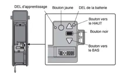
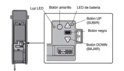
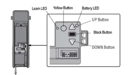
- The logic board interface features a black button for setup, UP/DOWN buttons for travel adjustment, and a Learn LED for status indication.
- The antenna must be routed through the channel in the battery cover to ensure proper operation.
Model compatibility
- Model 041DJ003MC replaces 050DCRJWF.
- Older LiftMaster remote controls are not compatible with this unit.
- Up to 40 Security+ 2.0 remote controls can be programmed.

Manual page author
Michael Turner
Technical manual editor
Reviews PDF manuals for structure, safety notes, and practical product details so readers can find the right information quickly.