Industrial / Door Operators
Installation Instructions for Dormakaba Saffire LX and Saffire EVO LZ Exit Device Operators
Comprehensive installation guide for Dormakaba Saffire LX and Saffire EVO LZ exit device operators. Includes step-by-step mounting instructions, hardware lists, wiring, and testing procedures.
Table of contents
Manual images
Click an image to enlargeImportant Information from the Manual
This document provides installation instructions for the Dormakaba Saffire LX and Saffire EVO LZ exit device operators. These instructions are intended for maintenance professionals or lock installers. Always wear safety glasses when drilling holes and ensure the door is properly prepared according to the specific drilling template for your lock model.
Recommended Tools
- Drill bits: 1/4", 5/16", 1/2", 3/4", 1-1/8"
- Phillips screwdriver (#2)
- Small flat screwdriver
- Hexagonal key 3mm / 1/8" (Allen Key)
Installation Steps
1. Install Key Cylinder (MKO Only)
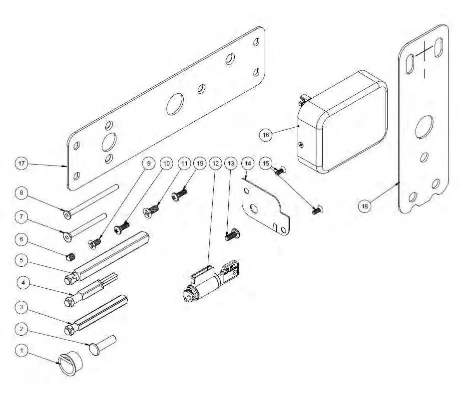
Insert the cylinder core into the key override housing. Secure the cylinder core using screw item 13. Place the access plate (item 14) over the housing and secure it with two screws (item 15).

2. Install Mounting Option
If using a secondary backplate (item 17), install the gasket (item 18) and secure the backplate using three screws (item 9) and one screw (item 11).
3. Install Lock Spindle
Insert the appropriate spindle (item 3, 4, or 5, depending on the exit device) into the front lock housing assembly until it clips securely.
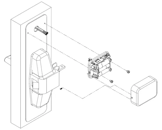
4. Install Lock Housing on the Door
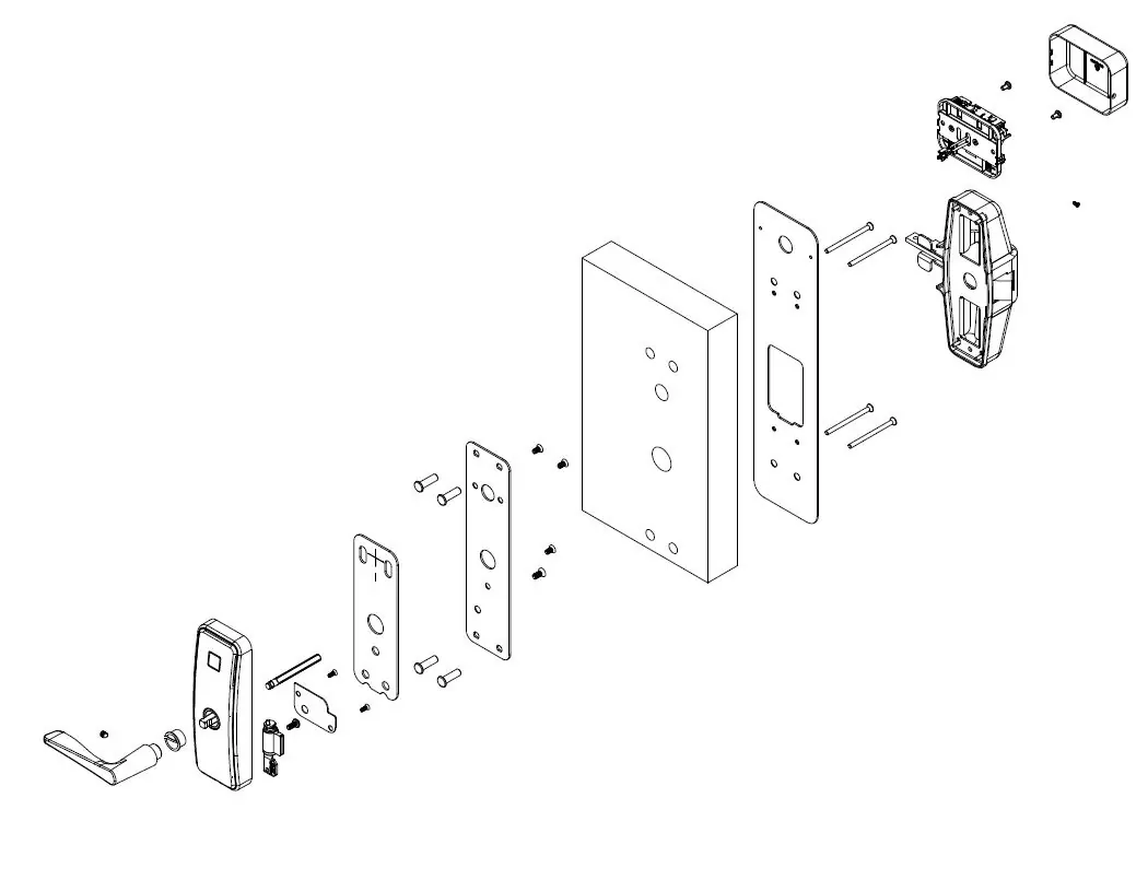
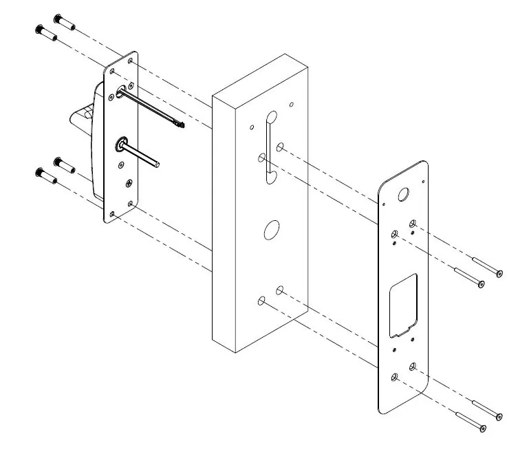
Ensure the door is prepared with the correct holes. Install the front lock housing with gasket (item 19), routing wire cables through the center hole and groove. Secure with the adaptor plate and three screws (item 7). Alternatively, if using a secondary backplate, secure the housing using four binding barrels (item 2) and four screws (item 8).
5. Install Exit Device
Refer to the exit device manufacturer's installation manual for specific steps. Note: For rim and concealed mount devices, proceed to step 5.6. For surface mount devices, proceed to step 5.7.
6. Connect Cables and Install Enclosure
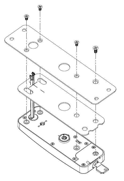
Connect cables to matching connectors and route excess cable back into the door hole. Secure the battery enclosure with the specified screws. Insert batteries, ensuring correct polarity, and reinstall the cover with the setscrew.
7. Install Outside Lever Handle
Install the outside bushing (item 1), ensuring it is snug. Attach the outside lever handle according to the lock handing (LH/RH) and secure it using the set screw (item 6).
Testing and Programming
Before testing, ensure the room door is open. Present a test keycard, verify that green and red lights flash, rotate the outside lever to check for bolt or rod retraction, and ensure the lever moves freely upon release. Push the panic bar to verify bolt or rod retraction. Refer to the Dormakaba access management system user manual for programming.
Technical Support
For technical assistance, call 1.877.468.3555 / +1.514.735 5410 or 1.800.999.6213 / +1.248.837.3700. You can also email [email protected].
Manufacturer information
dormakaba
Practical help
Common problems
Cable groove visible after assembly
Ensure proper installation of the surface vertical rod exit device using the required DT-516418-15 template.
Lock not functioning correctly
Verify battery installation and polarity; ensure cables are connected to matching connectors.
Before use
- Wear safety glasses when drilling holes.
- Verify door preparation and holes match the specific drilling template.
- Ensure the use of Alkaline batteries only.
- Check lock handing (LH/RH) before installing the lever handle.
- Ensure the outside bushing is snug.
Images and diagrams
- Exploded view diagrams are provided for standard mounting and secondary backplate mounting configurations.
- Specific diagrams illustrate the cable routing and battery enclosure installation for different exit device types.
Model compatibility
- All Surface Vertical Rod (SVR) exit devices require the use of template DT-516418-15.
- Refer to the match-up chart in the manual to identify the correct adapter plate and drilling template for specific exit device manufacturers (e.g., Detex, Dorma, Von Duprin, Precision, Arrow, Yale, Corbin Russwin, Hagar, Sargent, Monarch...

Manual page author
David Miller
Documentation analyst
Organizes user manual content into clear summaries, with attention to model details, product context, and everyday usability.