Industrial / Door Operators
User Manual for Dormakaba 90 09M Touchless Switch
Quick guide for the Dormakaba 90 09M Touchless Switch. Includes installation steps, wiring diagrams, DIP switch settings for unlock time and detection range, and operational instructions.
Table of contents
Manual images
Click an image to enlargeQuick Guide
The Dormakaba 90 09M is a touchless switch designed for access control. It features adjustable detection zones, configurable unlock times, and an optional buzzer. It supports both Fail Safe and Fail Secure lock configurations.
Installation
To install the switch:
- Gently grip the top of the front panel and unclip it. Slide towards the bottom to remove the front panel.
- Wire the device according to the wiring chart provided in the wiring section. A removable terminal block is included for convenience.
- Configure the DIP switches as required for your installation (see DIP Switch Settings).
- Secure the switch plate onto the mounting bracket or box using appropriate screws (2 x 6/32 x 1" screws are supplied).
- Reinstall the front panel by positioning the bottom catches in place, then lift and press the top until it clicks into place.
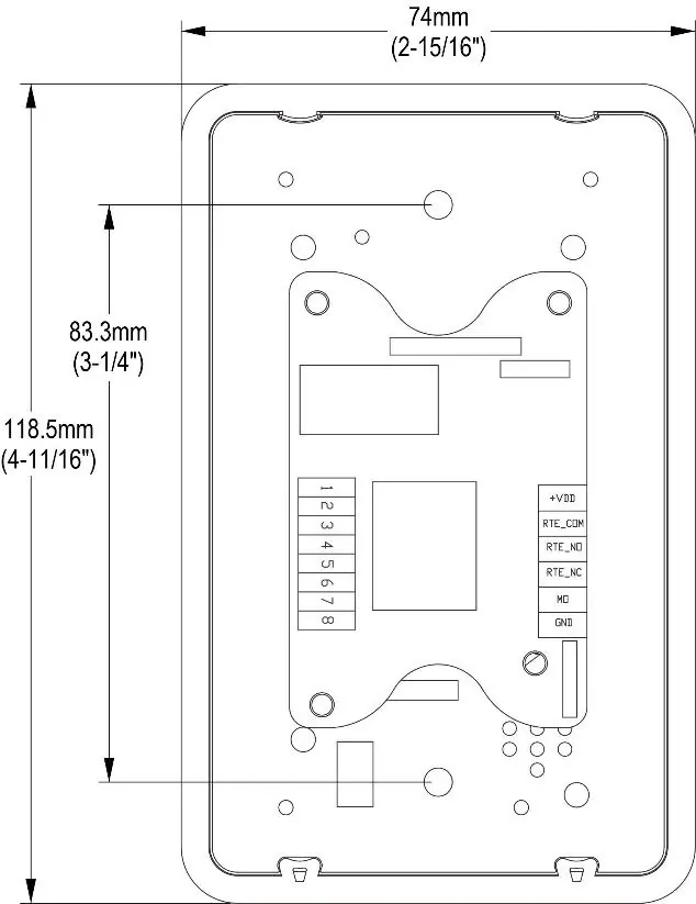
Wiring
The device uses a terminal block with the following connections:
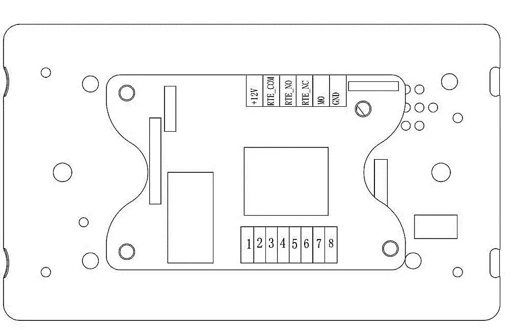
- +VDD: Positive (+12V~+24VDC) Input
- RTE_COM: Common for Exit Button Output
- RTE_NO: Normally Open Exit Button Output (Dry Contact)
- RTE_NC: Normally Closed Exit Button Output (Dry Contact)
- MO: Input for external device to trigger the door open (N/O)
- GND: Ground (0 VDC) Input
DIP Switch Settings
The DIP switches are located on the back of the unit and control the following functions:
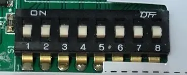
- Unlock Time (Switches 1-4): Set switches to ON to add time (1-15 seconds). SW1=1s, SW2=2s, SW3=4s, SW4=8s. Example: SW2 & SW4 ON = 10 seconds.
- Buzzer On/Off (Switch 5): SW5 OFF = Buzzer ON (default); SW5 ON = Buzzer OFF.
- Detection Zone (Switch 8): SW8 OFF = 50mm (default); SW8 ON = 20-30mm.
- Switches 6 & 7: Not in use.
Operation
To operate the switch, wave your hand near the sensor. An audible beep will sound (if enabled), the LED will turn green, and the relay will trigger for the configured unlock time. In the event of a power failure, the switch features a secondary mechanical override; press gently on the face of the switch to activate it as a standard press button.
Specifications
- Technology: Capacitive proximity sensor
- Detection Zone: 25-50mm (typical)
- Voltage: 12-24VDC (+/-10%)
- Output: Dry contact (SPDT) rated @ 30VDC/1Amp
- Operational Temperature: -20°C to +60°C
- Operating Humidity: 10%-90%
- Current Draw: 50mA (Standby), 115mA (Activated)
Manufacturer information
dormakaba
Practical help
Common problems
Switch not triggering
Verify power supply is 12-24VDC and wiring is correct. Ensure the detection zone is not obstructed.
Buzzer is too loud or unwanted
Set DIP switch 5 to ON to disable the buzzer.
Detection range is too sensitive
Set DIP switch 8 to ON to reduce the detection zone to 20-30mm.
Before use
- Ensure power supply is 12-24VDC.
- Verify wiring against the diagram on page 2.
- Configure DIP switches before mounting the unit.
- Ensure the front panel is properly clicked into place after installation.
Specs in practice
- Detection Zone
- The distance at which the sensor detects hand movement (20-50mm).
Images and diagrams
- Wiring Diagram: Shows connections for Power Supply, Fail Safe/Fail Secure locks, and external access control devices.
- DIP Switches: Located on the back, used to configure unlock time, buzzer, and detection range.
Model compatibility
- Compatible with 12-24VDC power supplies.
- Supports Fail Safe and Fail Secure lock configurations.
- Optional 433MHz wireless remote control receiver PCB available as an accessory.

Manual page author
Michael Turner
Technical manual editor
Reviews PDF manuals for structure, safety notes, and practical product details so readers can find the right information quickly.