Power / Uninterruptible Power Supplies
User Manual for Eaton Castle 1-3K G2 Online UPS
Quick guide for the Eaton Castle 1-3K G2 Online UPS. Includes installation, wiring, LCD settings, operation modes, maintenance, and troubleshooting.
Table of contents
Manual images
Click an image to enlargeQuick Guide from the Manual
The Eaton Castle 1-3K G2 is an online double-conversion UPS designed to protect critical equipment. Before first use, it is recommended to charge the internal batteries for at least 10 hours. Ensure the installation environment is cool, dry, and well-ventilated, maintaining at least 250mm of clearance behind the unit for heat dissipation. Always verify that the input voltage and power requirements match your local power grid.
Product Overview
This series includes tower (FG2) and rack-mount (RM) models ranging from 1KVA to 3KVA. The system features DSP digitization and high-frequency sine wave inversion to provide clean, stable power. It supports TN, IT, and TT power distribution systems.
Installation
Rack Installation: Use the optional rail kit. Install M5 floating nuts into the rack columns, adjust the rails to the cabinet depth, and secure them with M5 screws. Attach the mounting ears to the UPS sides before sliding the unit into the rails.
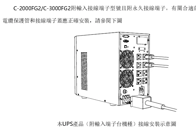
Wiring: Ensure the UPS is powered off during installation. Connect the input power cable to the appropriate outlet. For models with terminal blocks, ensure correct wire gauge (e.g., 12AWG or 10AWG depending on model) and torque (0.5Nm). Always connect the output devices to the UPS output terminals or sockets, ensuring the total load does not exceed the rated capacity.
Operation and LCD Panel
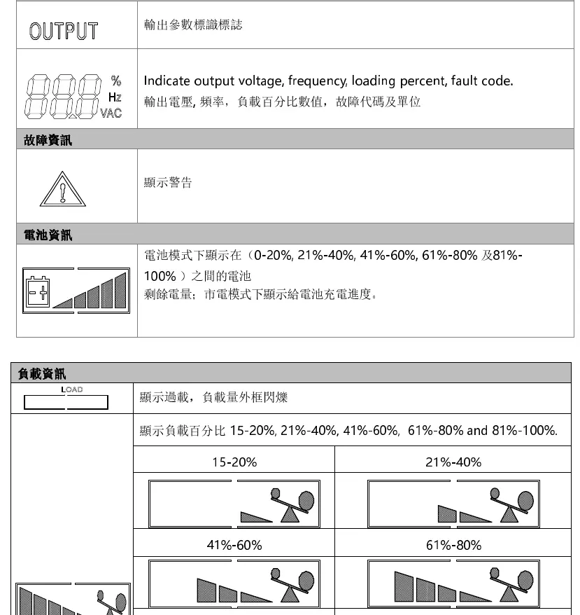
The LCD panel displays input/output parameters, load percentage, battery status, and fault codes. Use the buttons to navigate:
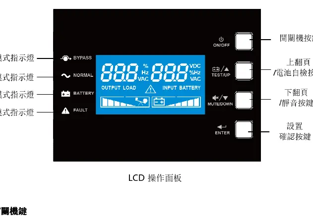
- On/Off Button: Long press for 3 seconds to power on or off.
- Enter Button: Long press for 5 seconds to enter settings mode.
- Up/Down Buttons: Used for page navigation, battery self-test, and silencing alarms.
Settings
In settings mode, you can configure:
- Output Voltage: 110V, 120V, or 125V.
- Output Frequency: Auto-sensing, 50Hz, or 60Hz.
- Auto-Restart (SON): Enable/Disable automatic startup when AC power returns.
- EPO/ROO: Configure Emergency Power Off and Remote On/Off settings.
- ECO Mode: Enable/Disable energy-saving mode.
- Bypass: Enable/Disable bypass output.
Maintenance
Battery Maintenance: The internal batteries are sealed lead-acid. Keep the environment between 15°C and 25°C. If the UPS is not used for a long period, charge it every 6 months. Under normal use, perform a battery discharge/charge cycle every 4-6 months. Battery replacement must be performed by authorized personnel.
Troubleshooting
If a fault occurs, check the fault code on the LCD:
- 01: Startup failure (check battery voltage).
- 10: Output short circuit (remove shorted device).
- 22: Overload (remove unnecessary loads).
- 23: Over-temperature (check ventilation, wait 10 minutes).
- 57: Battery not connected or weak.
Manufacturer information
Eaton
Practical help
Common problems
UPS fails to start
Check battery voltage; if low, charge for 10 hours. If the issue persists, contact support.
Output short circuit (Fault 10)
Turn off the UPS, remove the shorted device, and restart.
Overload (Fault 22)
Remove non-essential loads until the total load is below the rated capacity.
Over-temperature (Fault 23)
Ensure ventilation is not blocked, wait 10 minutes, and restart.
Before use
- Inspect for shipping damage.
- Ensure stable, ventilated installation space with 250mm clearance.
- Verify input voltage and power requirements.
- Charge internal batteries for 10 hours before first use.
- Ensure proper grounding of the input power source.
Specs in practice
- 1KVA/2KVA/3KVA
- Rated power capacity of the UPS model.
- 110/120/125Vac
- Supported input and output voltage range.
Images and diagrams
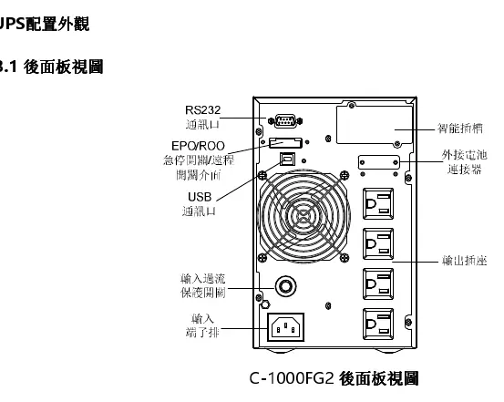
- Rear Panel: Shows input/output ports, communication slots (RS232/USB), and battery connectors.
- LCD Panel: Displays input/output parameters, load percentage, battery status, and fault codes.
Model compatibility
- Supports TN, IT, and TT power distribution systems.
- Compatible with WinPower monitoring software.
- Supports up to 4 external battery modules.

Manual page author
David Miller
Documentation analyst
Organizes user manual content into clear summaries, with attention to model details, product context, and everyday usability.