General / Accessories
Installation Guide for Danfoss EKE 2U Back up Power Module
Official installation and configuration guide for the Danfoss EKE 2U Back up Power Module. Includes wiring diagrams, DIN rail mounting instructions, controller parameter settings, and technical specifications for reliable energy storage.
Table of contents
Manual images
Jump to the sectionQuick guide from the manual
The Danfoss EKE 2U is an optional energy storage device designed to provide power to stepper controllers during a power failure, ensuring electronic valves can close safely. It is compatible with Danfoss EKE series and MCX controllers. Key operational aspects include the State of Health (SOH) function, which provides feedback on the module's status (Ready, Charging, Failed), and the Load Switch, which can be configured based on the number of valves connected.
Installation and Mounting
The EKE 2U module is designed for vertical mounting on a 35 mm DIN rail.
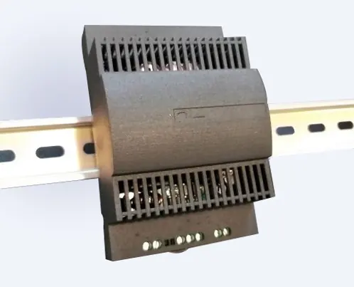
- Mounting: Snap the unit onto the DIN rail and secure it with a stopper to prevent sliding.
- Demounting: Gently pull the stirrup located at the base of the housing to release the unit from the rail.
- Environment: Ensure the device is installed inside an electrical panel with no live parts accessible. Avoid exposure to corrosive gases, high humidity (>90%), or strong vibrations.
Wiring and Connections
Proper wiring is critical for the module to function correctly.
- Power Supply: Use a class II category transformer for 24 V AC power supply.
- SOH Signal: Do not share the SOH signal between multiple controllers; connect it to only one EKE controller.
- Power Sharing: Power sharing is allowed between the EKE 2U and EKE SH controllers, provided the power supply is DC. A maximum of 2 EKE controllers can be connected to 1 EKE 2U.
- Cable Management: Keep power and battery backup cables separate from the SOH cable to avoid electromagnetic noise.
- Cable Length: Maximum cable length for power supply, backup output, and digital outputs is 5 meters.
Controller Configuration
To integrate the EKE 2U with EKE controllers, specific parameters must be set:
- Main Switch (R012): Ensure the main switch is OFF before changing settings.
- DI2 Configuration (O022): Set DI2 to 'PWR backup status' if the EKE 2U SOH is connected to DI2 of the controller.
- Battery Alarm (A034): Set to ON to receive alarms if the EKE 2U battery is low.
- Monitoring: Use parameter U101 to read actual battery voltage and U115 to read power backup status.
Technical Specifications
- Input Voltage: 24 V DC / 24 V AC (Range: 20-40 V DC, 19-29 V AC).
- Ambient Temperature: -25 °C to +60 °C.
- Protection Degree: IP 20.
- Charging Time: Approximately 2.5 minutes from a fully discharged state.
- Lifespan: >90,000 hours at 35 °C.
Safety and Warnings
This device contains live electrical components and must be installed by qualified personnel. The device must not be used as a safety device. Always disconnect the power supply before performing maintenance or working on electrical connections. Connecting output signals to mains voltage will permanently damage the controller.
Manufacturer information
Danfoss A/S
Practical help
Common problems
Failure LED flashing
The backup module is not working. The controller can still operate valves, but there is no guarantee that valves can close during a power loss.
Controller not detecting power failure
Connect the Power Failure (PF) signal to the controller only if the controller cannot detect power failure by itself.
SOH signal not working
Ensure the SOH signal is not shared between controllers; it must be connected to only one EKE controller.
Before use
- Verify supply voltage is 24V DC or 24V AC.
- Ensure DIN rail is 35mm.
- Check the valve type to determine the correct Load Switch position (POS A or POS B).
- Keep power and battery backup cables separate from the SOH cable.
- Ensure the installation environment is free from corrosive gases and excessive humidity.
Specs in practice
- Nominal input voltage
- 24 V DC / 24 V AC; the standard operating voltage for the module.
- Charging time
- ~2.5 minutes required to charge the module from a fully discharged state.
- Protection degree
- IP 20; indicates protection against solid objects but not water.
- Ambient temperature
- -25 °C to +60 °C; the operational temperature range for the device.
Images and diagrams
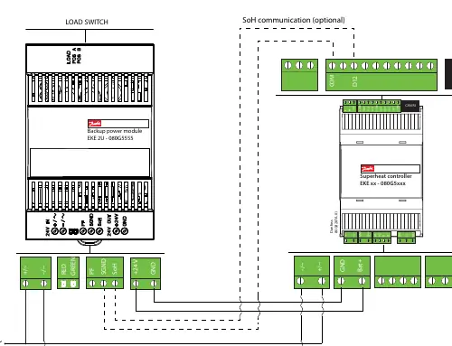
- Wiring diagram illustrates connections for the Load Switch, SOH communication, and power supply.
- Mounting diagram shows the snap-on mechanism for the 35mm DIN rail.
- Demounting diagram shows the use of a tool to pull the stirrup for removal.
Model compatibility
- Compatible with Danfoss EKE series and MCX controllers.
- Compatible with Danfoss stepper motor valves (ETS 5M/6, ETS Colibri, ETS 12.5-400, KVS 15/42, CCMT/CCM).

Manual page author
Emily Carter
User documentation editor
Prepares concise manual descriptions and highlights the most useful setup, operation, and maintenance information for readers.